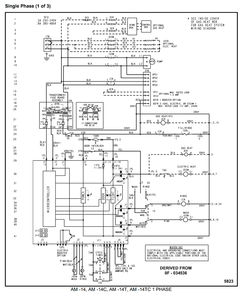
When it comes to understanding the electrical system of your Yamaha outboard motor, having a comprehensive 703 Yamaha Remote Control Wiring Diagram is essential. This diagram serves as a roadmap, guiding you through the various electrical components and connections within the remote control system.
Why are 703 Yamaha Remote Control Wiring Diagrams essential?
- Help to identify and locate specific wires and components
- Aid in troubleshooting electrical issues
- Ensure proper installation and maintenance of the remote control system
How to read and interpret 703 Yamaha Remote Control Wiring Diagrams effectively
Reading and interpreting wiring diagrams may seem daunting at first, but with a little guidance, you’ll be able to navigate through them with ease. Here are some tips:
- Start by familiarizing yourself with the symbols and color codes used in the diagram
- Follow the flow of the diagram to understand the sequence of electrical connections
- Pay attention to labels and legends for clarity on component identification
Using 703 Yamaha Remote Control Wiring Diagrams for troubleshooting electrical problems
When faced with electrical issues in your Yamaha outboard motor, the wiring diagram can be your best friend. Here’s how you can use it for troubleshooting:
- Identify the specific circuit or component related to the problem
- Trace the wiring to locate any potential faults or breaks
- Refer to the diagram to understand how the electrical system should be functioning
It’s crucial to approach electrical work with caution and prioritize safety above all else. Here are some safety tips and best practices to keep in mind:
- Always disconnect the battery before working on any electrical components
- Use insulated tools to prevent electrical shocks
- Double-check all connections before powering up the system
- If unsure, seek professional help to avoid any risks of electrical hazards
703 Yamaha Remote Control Wiring Diagram
Yamaha 703 Remote Control Wiring Diagram

Yamaha 703 Remote Control Box Wiring Diagram – properinspire

Yamaha 703 Remote Control Box Wiring Diagram – properinspire
The Ultimate Guide to Understanding Yamaha 703 Remote Control Wiring

Yamaha 703 Remote Control Box Wiring Diagram – Circuit Diagram
