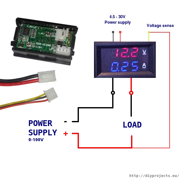
When it comes to understanding the flow of electrical current in a vehicle or any electrical system, an Ammeter Wiring Diagram is a valuable tool. This diagram provides a visual representation of how the electrical current travels through the system, helping mechanics and technicians troubleshoot issues and make necessary repairs.
Why Are Ammeter Wiring Diagrams Essential?
Ammeter Wiring Diagrams are essential for several reasons:
- They help identify the various components in the electrical system.
- They show the direction of current flow and how components are connected.
- They assist in diagnosing electrical problems quickly and accurately.
How to Read and Interpret Ammeter Wiring Diagrams
Reading and interpreting Ammeter Wiring Diagrams may seem daunting at first, but with some guidance, it can be straightforward:
- Start by identifying the key components in the diagram, such as the battery, alternator, and various electrical devices.
- Follow the lines to see how the current flows from one component to another.
- Pay attention to symbols and colors used in the diagram to understand the connections better.
Using Ammeter Wiring Diagrams for Troubleshooting Electrical Problems
When faced with electrical issues in a vehicle or any electrical system, an Ammeter Wiring Diagram can be a lifesaver:
- Trace the current flow in the diagram to identify where the problem might be occurring.
- Check for any breaks or loose connections in the wiring that could be causing the issue.
- Compare the diagram with the actual wiring in the vehicle to pinpoint the exact location of the problem.
Importance of Safety When Working with Ammeter Wiring Diagrams
Working with electrical systems can be dangerous if proper precautions are not taken. Here are some safety tips to keep in mind:
- Always disconnect the battery before working on any electrical components.
- Use insulated tools to prevent electric shocks.
- Avoid working on electrical systems in wet or damp conditions to prevent accidents.
Ammeter Wiring Diagram
Digital Ammeter Wiring With Current Transformer – CT Coil – Electrical
Ammeter Connection Diagram with Selector Switch and CT – ETechnoG

How to wire digital dual display volt- and ammeter – DIY Projects

What is an Ammeter? Symbol, Circuit Diagram, Types and Applications

How to Setup a Digital Volt Amp Meter Wire Connection – YouTube

Digital Ammeter Wiring Diagram and Connection with CT – ETechnoG
 Phase Digital Ammeter Connection Diagram with CT.png)