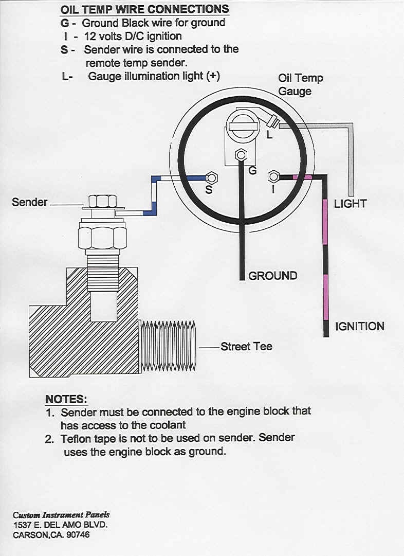
Autometer Gauge Wiring Diagram
An Autometer Gauge Wiring Diagram is a detailed schematic that illustrates the wiring connections for Autometer gauges in a vehicle. These diagrams are essential for properly installing and troubleshooting Autometer gauges to ensure they function correctly.
Importance of Autometer Gauge Wiring Diagram
- Ensure proper installation of Autometer gauges
- Prevent electrical issues and malfunctions
- Maximize gauge performance
- Facilitate troubleshooting
Reading and Interpreting Autometer Gauge Wiring Diagram
When looking at an Autometer Gauge Wiring Diagram, it’s important to understand the symbols and color codes used. The diagram typically includes information on where each wire should be connected, the gauge’s power source, ground connection, and any additional components.
Using Autometer Gauge Wiring Diagram for Troubleshooting
Automater Gauge Wiring Diagrams are invaluable when troubleshooting electrical problems with Autometer gauges. By following the diagram, you can easily identify any wiring issues, faulty connections, or component failures that may be causing the problem.
Safety Tips for Working with Autometer Gauge Wiring Diagram
- Always disconnect the vehicle’s battery before working on the electrical system
- Use insulated tools to prevent electrical shocks
- Avoid working on wiring in wet or damp conditions
- Double-check all connections before powering up the gauges
By following these safety tips and utilizing Autometer Gauge Wiring Diagrams effectively, you can ensure a safe and successful installation of Autometer gauges in your vehicle.
Autometer Gauge Wiring Diagram
Autometer Pro Shift Light Wiring Diagram – Diysus

Autometer Oil Pressure Gauge Wiring Diagram

Autometer Temperature Gauge Wiring Diagram – Wiring Diagram

Autometer Tach Wiring V8 – Unity Wiring

Autometer Wiring Diagrams

Auto Meter Temp Gauge Wiring Diagram
