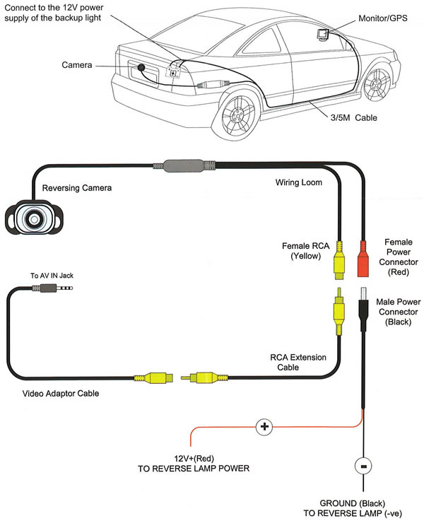
Car Reverse Camera Wiring Diagrams are crucial tools for understanding the electrical connections in your vehicle’s reverse camera system. By following these diagrams, you can easily identify the wiring layout and make necessary repairs or modifications. Understanding how to interpret these diagrams can save you time and money, as well as ensure a safe and effective installation process.
Why Car Reverse Camera Wiring Diagrams are essential
- Helps in understanding the wiring connections
- Aids in troubleshooting electrical issues
- Ensures proper installation of the reverse camera system
- Prevents damage to the vehicle’s electrical system
How to read and interpret Car Reverse Camera Wiring Diagrams effectively
When looking at a wiring diagram for a car reverse camera, it’s important to pay attention to the following key elements:
- Color coding of wires
- Identification of connectors and components
- Understanding of symbols and abbreviations
- Following the flow of electrical current
Using Car Reverse Camera Wiring Diagrams for troubleshooting electrical problems
Car Reverse Camera Wiring Diagrams can be invaluable when diagnosing and fixing electrical issues in your vehicle. By following the diagram, you can pinpoint the source of the problem and make the necessary repairs. Common issues that can be resolved using these diagrams include:
- Broken or damaged wires
- Faulty connectors or connections
- Incorrect installation of the reverse camera system
- Short circuits or electrical malfunctions
Importance of safety when working with electrical systems
When working with car reverse camera wiring diagrams or any electrical system, it’s important to prioritize safety. Here are some tips to keep in mind:
- Always disconnect the vehicle’s battery before working on the electrical system
- Use insulated tools to prevent electrical shocks
- Avoid working on the wiring system in wet or damp conditions
- Double-check all connections before reassembling the components
Car Reverse Camera Wiring Diagram
Wireless Reversing Camera Wiring Diagram

How to install a back up camera? – Professional blog for car DVD GPS

Wireless Reversing Camera Wiring Diagram

Car Reverse Camera Wiring Diagram

17 Car Reverse Camera Wiring Diagram Reverse Camera For Car, Backup
