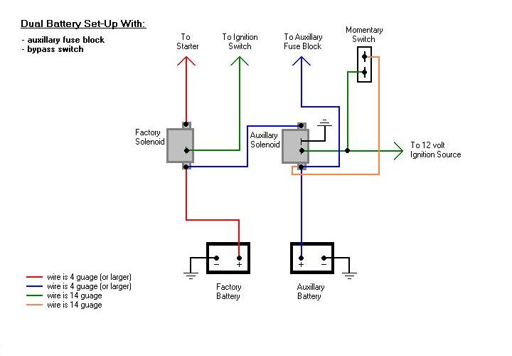
Continuous Duty Solenoid Wiring Diagrams are essential tools for understanding the electrical connections and configurations of solenoids in various systems. Whether you are a novice DIY enthusiast or a seasoned mechanic, having a clear understanding of these diagrams can help you troubleshoot and fix electrical issues effectively.
Importance of Continuous Duty Solenoid Wiring Diagrams
- Provide a visual representation of the electrical connections
- Help in identifying the components of the solenoid system
- Aid in diagnosing and resolving electrical problems
Reading and Interpreting Continuous Duty Solenoid Wiring Diagrams
When looking at a wiring diagram for a continuous duty solenoid, it is important to pay attention to the following key elements:
- Color coding of wires
- Symbols representing different components
- Direction of current flow
Using Continuous Duty Solenoid Wiring Diagrams for Troubleshooting
Continuous Duty Solenoid Wiring Diagrams can be invaluable when trying to troubleshoot electrical problems. By following the diagram and checking the connections, you can easily identify any faulty wires, connections, or components. This can save you time and effort in diagnosing and fixing the issue.
Safety Tips for Working with Continuous Duty Solenoid Wiring Diagrams
- Always disconnect the power source before working on any electrical system
- Use insulated tools to avoid electric shock
- Double-check your work before reapplying power to the system
- If you are unsure about any aspect of the wiring diagram, consult a professional mechanic or electrician
Continuous Duty Solenoid Wiring Diagram
Continuous Duty Solenoid Wiring Diagram – Artled

Cole Hersee Continuous Duty Solenoid Wiring Diagram – Herbally

Cole Hersee Continuous Duty Solenoid Wiring Diagram – Wiring Digital
12 Volt Continuous Duty Solenoid Wiring Diagram

12 Volt Continuous Duty Solenoid Wiring Diagram » Wiring Digital And
