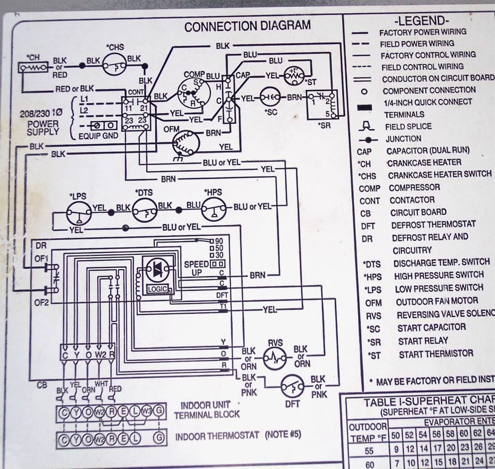
Understanding the Copeland Compressor Wiring Diagram is crucial for any mechanic or technician working with HVAC systems. These diagrams provide a visual representation of the electrical connections within the compressor, helping to ensure proper installation and troubleshooting.
Why Copeland Compressor Wiring Diagrams are Essential
Here are a few reasons why these diagrams are essential:
- Ensure correct installation of the compressor
- Aid in troubleshooting electrical issues
- Help in identifying faulty components
How to Read and Interpret Copeland Compressor Wiring Diagrams
When looking at a Copeland Compressor Wiring Diagram, it’s important to understand the symbols and labels used. Here are some tips for effective interpretation:
- Identify the power supply lines
- Locate the start and run terminals
- Understand the connection between the compressor and other components
Using Copeland Compressor Wiring Diagrams for Troubleshooting
When faced with electrical problems in an HVAC system, the wiring diagram can be a valuable tool. Here’s how you can use it for troubleshooting:
- Check for continuity in the wiring connections
- Verify proper voltage levels at each terminal
- Follow the wiring diagram to trace the source of the issue
Importance of Safety When Working with Copeland Compressor Wiring Diagrams
Working with electrical systems can be dangerous, so it’s essential to follow safety precautions when using wiring diagrams. Here are some safety tips to keep in mind:
- Always turn off the power supply before working on any electrical components
- Use insulated tools to prevent electric shock
- Double-check your work before restoring power to the system
Copeland Compressor Wiring Diagram
3 Phase Copelandpressor Wiring Diagrams

The Ultimate Guide to Understanding Copeland Compressor Wiring Diagrams

[DIAGRAM] 3 Phase Copeland Compressor Wiring Diagrams – MYDIAGRAM.ONLINE
![Copeland Compressor Wiring Diagram [DIAGRAM] 3 Phase Copeland Compressor Wiring Diagrams - MYDIAGRAM.ONLINE](http://schematron.org/image/copeland-compressor-wiring-diagram-7.jpg)
Wiring Diagram PDF: 120 Volt Copeland Compressor Wiring Diagram

Hvac Compressor Wiring Diagram

Copeland Compressor Wiring Diagram
