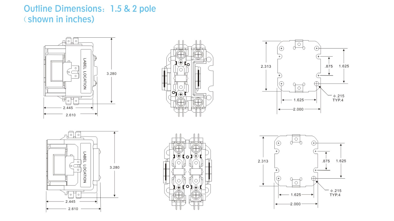
When it comes to electrical systems, having a clear understanding of the Definite Purpose Contactor Wiring Diagram is crucial. These diagrams provide a visual representation of how the various components of a definite purpose contactor are connected and help ensure that the system functions properly.
Why Definite Purpose Contactor Wiring Diagrams are Essential
- Ensure proper installation of electrical components
- Prevent electrical malfunctions
- Aid in troubleshooting electrical issues
- Comply with safety regulations
How to Read and Interpret Definite Purpose Contactor Wiring Diagrams
Reading and interpreting definite purpose contactor wiring diagrams may seem daunting at first, but with a little practice, it becomes easier. Here are some tips to help you effectively understand these diagrams:
- Identify the components: Familiarize yourself with the symbols used in the diagram to represent different components.
- Follow the flow: Pay attention to the direction of the wires and how they are connected to each component.
- Understand the labeling: Make sure you understand the labeling of each component and wire to avoid confusion.
Using Definite Purpose Contactor Wiring Diagrams for Troubleshooting
Definite purpose contactor wiring diagrams are invaluable when it comes to troubleshooting electrical problems. By following the diagram, you can easily identify where the issue lies and take the necessary steps to fix it. Here’s how you can use these diagrams for troubleshooting:
- Locate the problem area: Use the diagram to pinpoint the exact location of the issue within the electrical system.
- Check connections: Ensure that all connections are secure and properly made according to the diagram.
- Test components: Use a multimeter to test the continuity and functionality of each component as indicated in the diagram.
Importance of Safety
Working with electrical systems can be dangerous, so it’s essential to prioritize safety at all times. Here are some safety tips and best practices to keep in mind when using definite purpose contactor wiring diagrams:
- Always turn off the power before working on any electrical system.
- Wear appropriate personal protective equipment, such as gloves and safety goggles.
- Double-check all connections before turning the power back on to prevent electrical hazards.
- If you’re unsure about any aspect of the wiring diagram, consult a professional electrician for assistance.
Definite Purpose Contactor Wiring Diagram
How To Connect A Contactor Diagram – Wiring Draw And Schematic
How to Wire an Eaton Definite Purpose Contactor: A Step-by-Step Wiring

30 Definite Purpose Contactor Wiring Diagram – Wire Diagram Source

Contactor Coil Wiring Diagram

Contactor Wiring Diagram Single Phase
Understanding The Basics Of 240 Volt Contactor Wiring Diagrams – WIREGRAM
