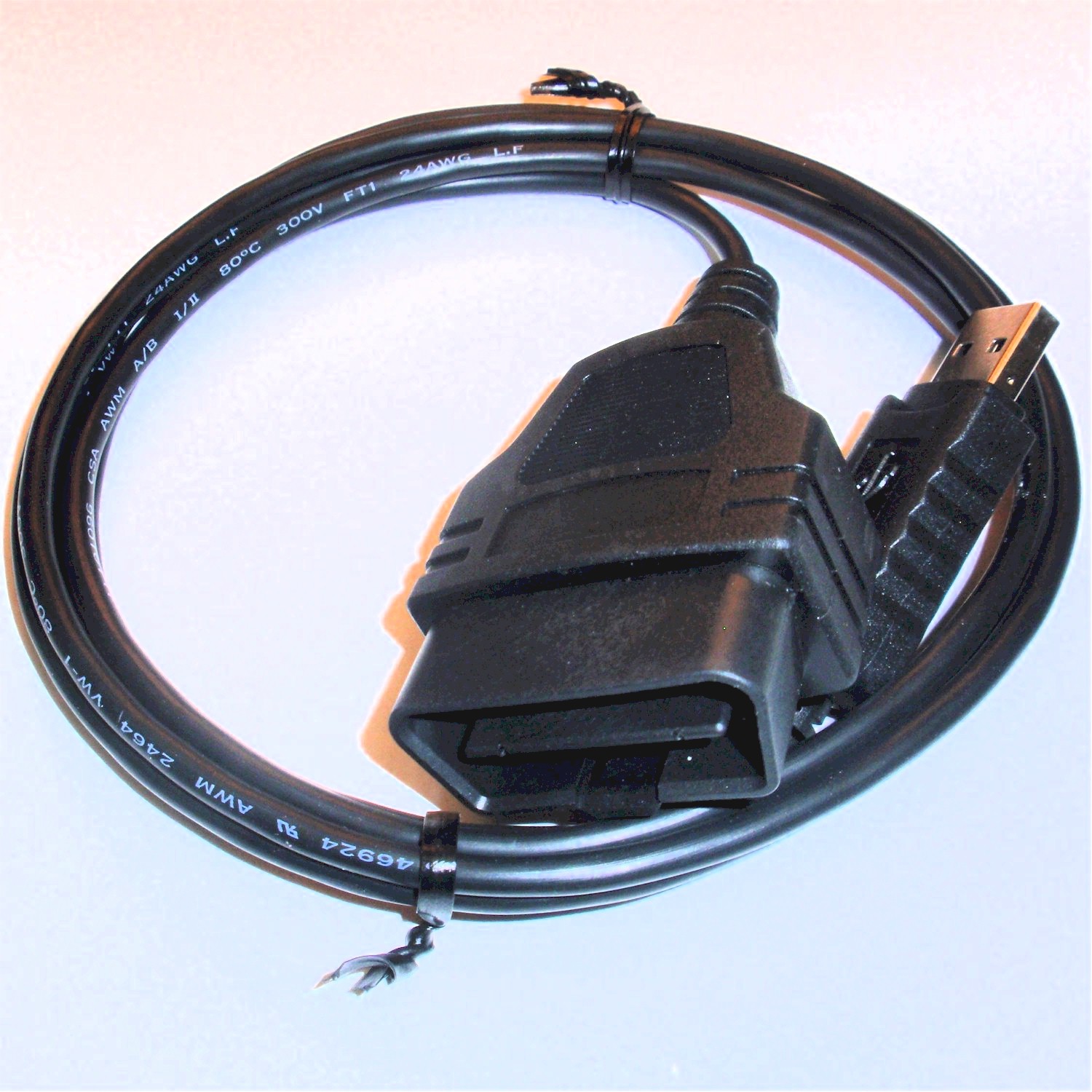
Diy Obd2 To Usb Wiring Diagram
When working on a vehicle’s electrical system, having a Diy Obd2 To Usb Wiring Diagram can be incredibly helpful. This diagram provides a visual representation of the wiring connections between the OBD2 port and a USB connector, allowing you to easily understand and troubleshoot any issues that may arise.
Why Diy Obd2 To Usb Wiring Diagram are essential:
- Helps in understanding the wiring connections between OBD2 and USB ports
- Allows for easy troubleshooting of electrical issues
- Provides a visual guide for making necessary repairs or modifications
- Can save time and money by avoiding guesswork
How to read and interpret Diy Obd2 To Usb Wiring Diagram:
- Start by identifying the OBD2 and USB ports on the diagram
- Follow the lines connecting the ports to understand the wiring connections
- Pay attention to any labels or color codes used in the diagram
- Refer to the legend or key if available to understand the symbols used
Using Diy Obd2 To Usb Wiring Diagram for troubleshooting electrical problems:
- Identify the specific area of the wiring that may be causing the issue
- Follow the wiring connections in the diagram to locate any potential faults or breaks
- Use a multimeter to test the continuity of the wires and connectors
- Refer to the diagram to make any necessary repairs or modifications
It is important to always prioritize safety when working with electrical systems and using wiring diagrams. Here are some safety tips and best practices to keep in mind:
- Always disconnect the vehicle’s battery before working on the electrical system
- Use insulated tools to avoid the risk of electric shock
- Avoid working on the wiring when the vehicle is running
- Double-check all connections before reassembling the system
Diy Obd2 To Usb Wiring Diagram
Diy Obd2 To Usb Wiring Diagram

Usb Wiring Diagram Homemade Obd2 To Usb Cable – Building A Tuneecu

Diy Obd2 To Usb Wiring Diagram Auto Repair Manuals: Obd Ii To Usb Cable
Usb Wiring Diagram Homemade Obd2 To Usb Cable – Building A Tuneecu

Burger Waren Plus obd2 to usb wiring diagram Besichtigung Nationale

Obd2 To Usb Wiring Diagram – whats popular
