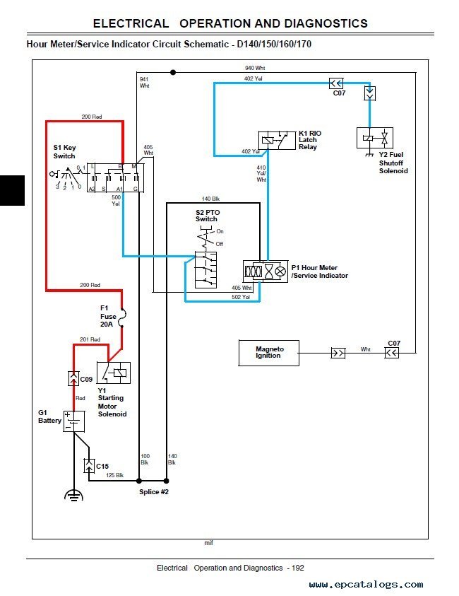
Electrical Schematic John Deere 100 Series Wiring Diagrams are detailed diagrams that show the electrical connections and wiring for John Deere 100 Series tractors. These diagrams are essential for anyone working on electrical systems in these tractors, as they provide a visual representation of the wiring layout and help in troubleshooting electrical issues.
Why are Electrical Schematic John Deere 100 Series Wiring Diagrams essential?
- Provide a visual representation of the wiring layout
- Aid in understanding the electrical connections
- Help in troubleshooting electrical issues
- Ensure proper installation of electrical components
How to read and interpret Electrical Schematic John Deere 100 Series Wiring Diagrams effectively
Reading and interpreting these diagrams can be daunting for beginners, but with practice, it becomes easier. Here are some tips to help you:
- Start by familiarizing yourself with the symbols used in the diagram
- Follow the flow of the wiring from one component to another
- Refer to the legend or key to understand the symbols and colors used
- Take your time to study and analyze the diagram thoroughly
How Electrical Schematic John Deere 100 Series Wiring Diagrams are used for troubleshooting electrical problems
These diagrams play a crucial role in troubleshooting electrical issues in John Deere 100 Series tractors. Here’s how they can help:
- Identify the location of components and their connections
- Trace the flow of electricity to pinpoint the issue
- Compare the actual wiring with the diagram to find discrepancies
- Test electrical connections and components based on the information provided
Safety is paramount when working with electrical systems and using wiring diagrams. Always follow these safety tips and best practices:
- Disconnect the power source before working on any electrical components
- Use insulated tools to prevent electric shock
- Avoid working on electrical systems in wet or damp conditions
- Double-check your work before reapplying power to the system
Electrical Schematic John Deere 100 Series Wiring Diagram
Electrical Schematic John Deere 100 Series Wiring Diagram

John Deere L100 L110 L120 L130 Lawn Tractors Repair Manual PDF

John Deere 100 Series Wiring Diagram – Blogid

John Deere 100 Series Wiring Diagram – Wiring Digital and Schematic

John Deere La115 Wiring Diagram – Naturalied

John Deere La105 Wiring Schematic – Wiring Diagram
