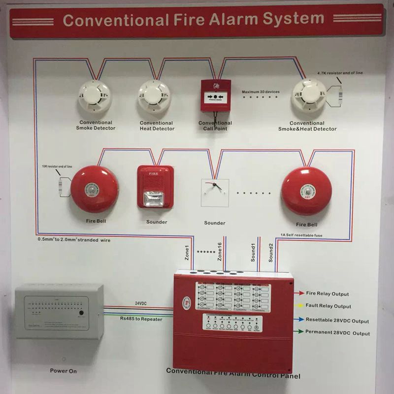
Fire Detector Wiring Diagrams are essential tools for understanding the electrical connections and components of fire detection systems. These diagrams provide a visual representation of the wiring layout, which helps technicians and installers properly install, maintain, and troubleshoot fire detectors.
Importance of Fire Detector Wiring Diagrams
- Ensure proper installation of fire detection systems
- Help identify and troubleshoot wiring issues
- Aid in understanding the interconnections between different components
Reading and Interpreting Fire Detector Wiring Diagrams
When reading a fire detector wiring diagram, it’s important to understand the symbols and color codes used to represent various components and connections. Pay attention to the legends and labels to correctly interpret the diagram. Follow the lines to trace the wiring path and connections between devices.
Using Fire Detector Wiring Diagrams for Troubleshooting
Fire detector wiring diagrams are valuable tools for troubleshooting electrical problems. By following the wiring diagram, technicians can identify faulty connections, short circuits, or damaged components. This helps in diagnosing the issue accurately and making necessary repairs.
Safety Tips for Working with Fire Detector Wiring Diagrams
- Always turn off the power supply before working on electrical systems
- Use insulated tools to prevent electrical shocks
- Double-check the wiring connections before powering up the system
- Wear appropriate safety gear, such as gloves and safety glasses
- Seek professional help if unsure about any aspect of the wiring diagram
Fire Detector Wiring Diagram
️Fire Alarm Installation Wiring Diagram Free Download| Gmbar.co

️Conventional Fire Alarm System Wiring Diagram Pdf Free Download

Fire Alarm System: Wiring Diagram Of Fire Alarm System

Wiring Diagram For Fire Alarm Panel – Wiring Digital and Schematic

Fire Alarm System Wiring Diagram ~ ELECTRICAL KNOWLEDGE

⭐ 4 Wire Smoke Detector Wiring Diagram Vista 20 ⭐ – Smoke fire kerosene
