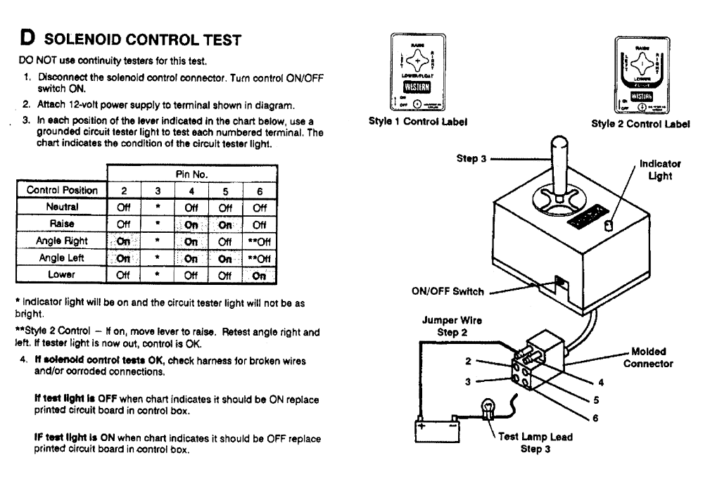
When it comes to ensuring the smooth operation of your Fisher plow system, understanding the Fisher Plow Controller Wiring Diagram is crucial. This diagram serves as a roadmap for the electrical connections within your plow system, allowing you to troubleshoot issues and make necessary repairs.
Why Fisher Plow Controller Wiring Diagrams are Essential
The Fisher Plow Controller Wiring Diagram is essential for a variety of reasons:
- Helps you understand the electrical connections within your plow system
- Assists in troubleshooting electrical issues
- Guides you in making repairs or modifications to the wiring
How to Read and Interpret Fisher Plow Controller Wiring Diagrams
Reading and interpreting Fisher Plow Controller Wiring Diagrams may seem daunting at first, but with a little guidance, you’ll be able to make sense of them:
- Identify the key components and connections on the diagram
- Follow the wiring paths to understand how the electrical system is connected
- Refer to the legend or key to understand the symbols and colors used in the diagram
Using Fisher Plow Controller Wiring Diagrams for Troubleshooting
When faced with electrical problems in your Fisher plow system, the Wiring Diagram can be a valuable tool for troubleshooting:
- Identify any loose or damaged connections
- Check for continuity and voltage at various points in the system
- Trace the wiring to locate any short circuits or grounds
Importance of Safety
Working with electrical systems can be dangerous, so it’s important to prioritize safety:
- Always disconnect the power source before working on the wiring
- Use insulated tools to prevent electric shocks
- Avoid working on wet or damp surfaces to prevent electrical hazards
By following these safety tips and using the Fisher Plow Controller Wiring Diagram effectively, you can ensure the safe and efficient operation of your plow system.
Fisher Plow Controller Wiring Diagram
Fisher Plow Wiring Diagram Troubleshooting – wiring diagram creator

Fisher Snow Plow Wiring Diagram Pdf – Wiring Diagram and Schematic
Fisher Plow Controller Wiring Diagram
Fisher Snow Plow Controller Wiring Diagram – Wiring Diagram
Fisher Plow Control Wiring Diagram

How to Properly Wire a Fisher Snow Plow Controller: A Step-by-Step
