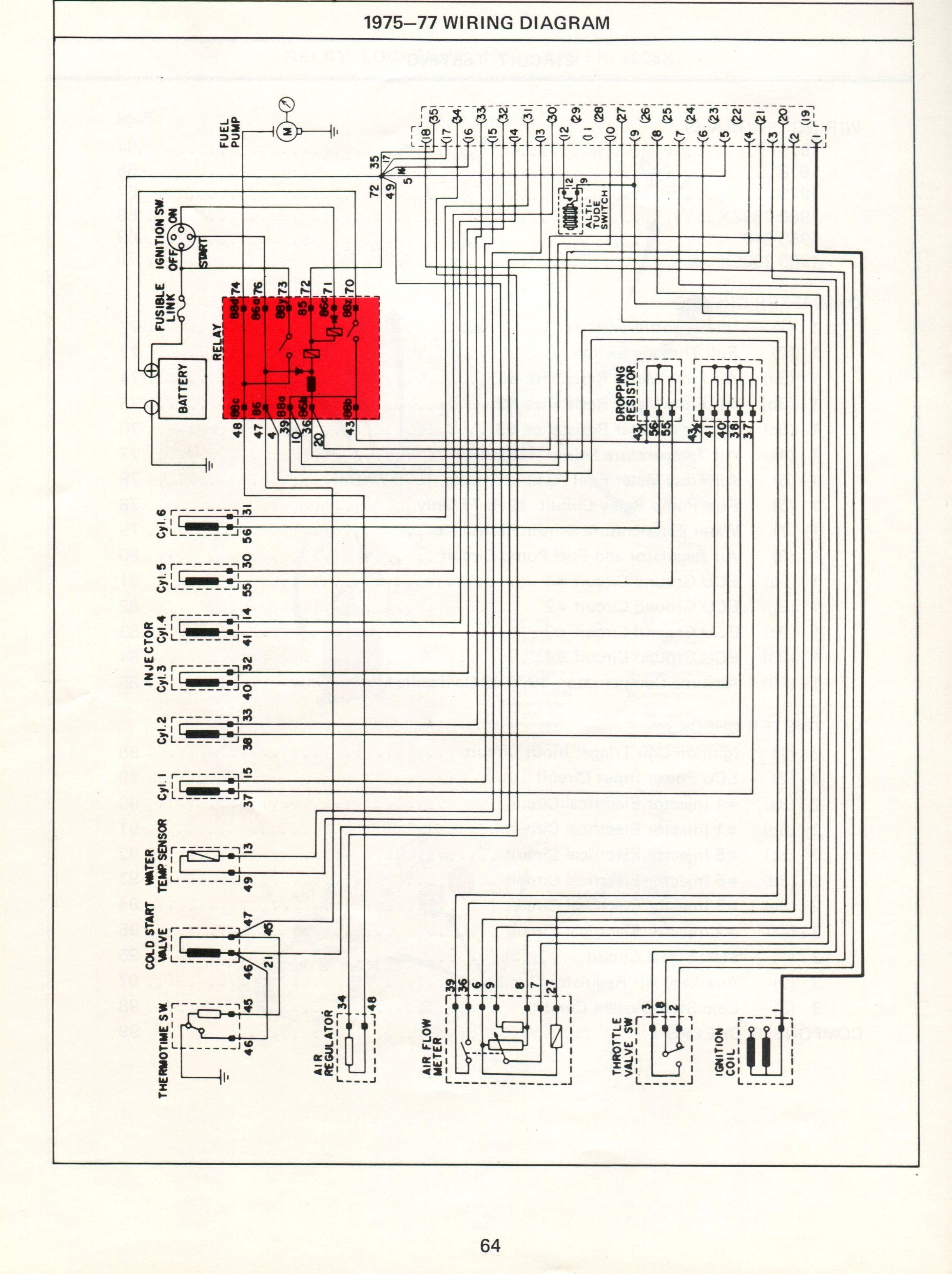
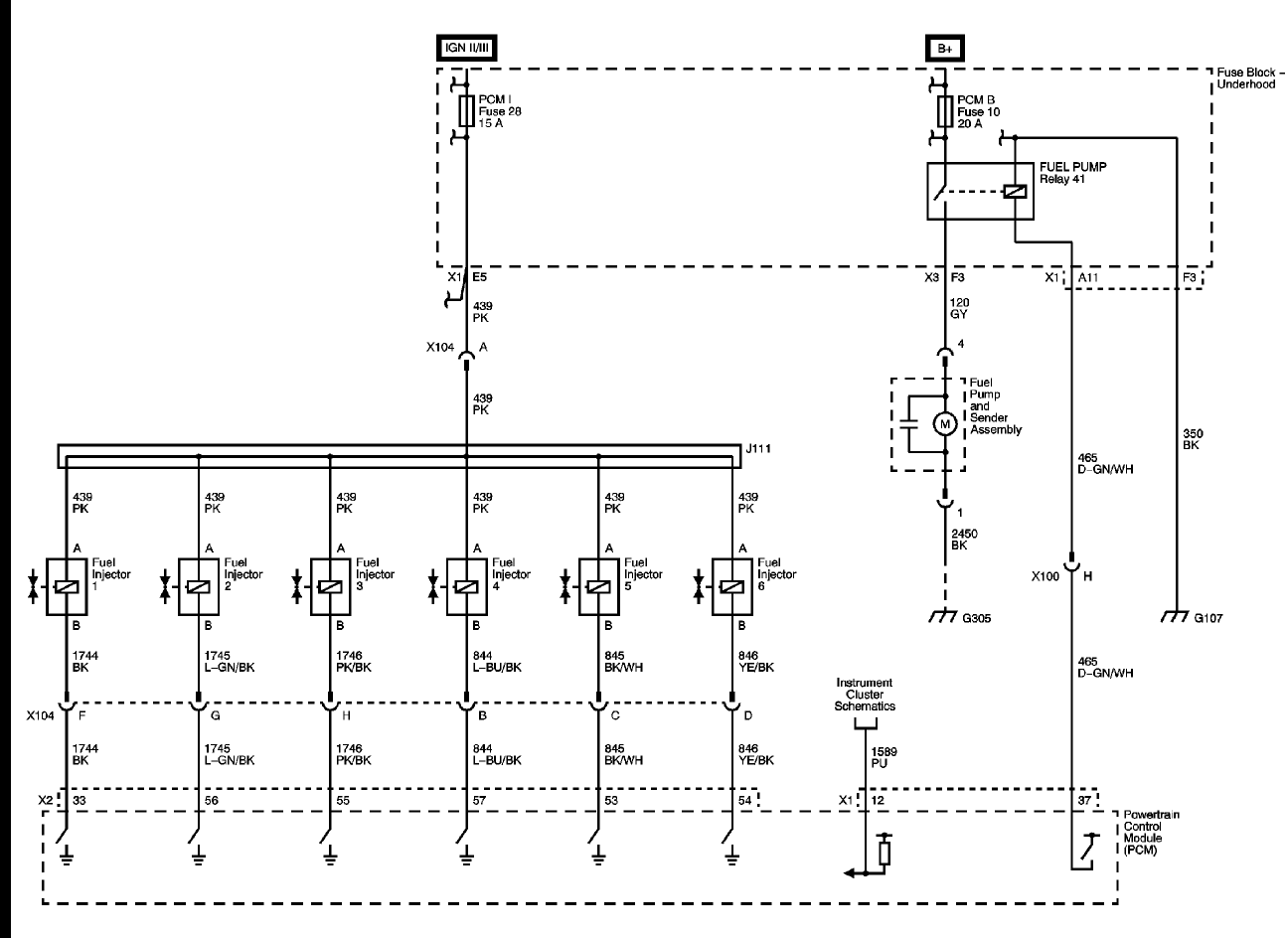
Understanding how to interpret a Fuel Injection Wiring Diagram is crucial for any automotive mechanic. These diagrams provide a visual representation of the vehicle’s fuel injection system, showing the wiring connections between various components such as sensors, injectors, and the Engine Control Module (ECM). By studying these diagrams, mechanics can easily identify electrical issues, troubleshoot problems, and make necessary repairs to ensure the vehicle runs smoothly.
Why Fuel Injection Wiring Diagrams are Essential
Fuel Injection Wiring Diagrams are essential for several reasons:
- Help in understanding the layout of the fuel injection system
- Show the connection points between different components
- Aid in diagnosing electrical issues quickly and accurately
- Ensure proper installation and repair of wiring connections
How to Read and Interpret Fuel Injection Wiring Diagrams Effectively
When reading a Fuel Injection Wiring Diagram, it’s important to pay attention to the symbols and color codes used. Here are some tips to help you interpret these diagrams effectively:
- Start by identifying the key components such as sensors, injectors, and the ECM
- Follow the wiring paths to understand how the components are connected
- Refer to the legend or key provided with the diagram to understand the symbols used
- Use a multimeter to test the continuity of the wiring connections
Using Fuel Injection Wiring Diagrams for Troubleshooting Electrical Problems
When troubleshooting electrical problems in a vehicle, Fuel Injection Wiring Diagrams are invaluable tools. By following the wiring diagram and conducting tests on the various components, mechanics can pinpoint the source of the issue and take appropriate action to resolve it. Whether it’s a faulty sensor, a broken wire, or a malfunctioning ECM, these diagrams provide a roadmap to solving the problem efficiently.
Importance of Safety and Best Practices
Working with electrical systems can be dangerous if proper precautions are not taken. Here are some safety tips and best practices to keep in mind when using Fuel Injection Wiring Diagrams:
- Always disconnect the battery before working on any electrical components
- Use insulated tools to prevent electric shocks
- Avoid working on the wiring system when the engine is running
- Double-check all connections before reassembling the components
Fuel Injection Wiring Diagram
Holley Multiport Fuel Injection Wiring Diagram

Electronic Fuel Injection System – Tholibs

Datsun Electronic Fuel Injection – Wiring Diagrams

Datsun Electronic Fuel Injection – Wiring Diagrams

Fuel Injector Wiring Harness Diagram

10' MegaSquirt Electronic Fuel Injection Wiring Harness (MS1 / MS2
