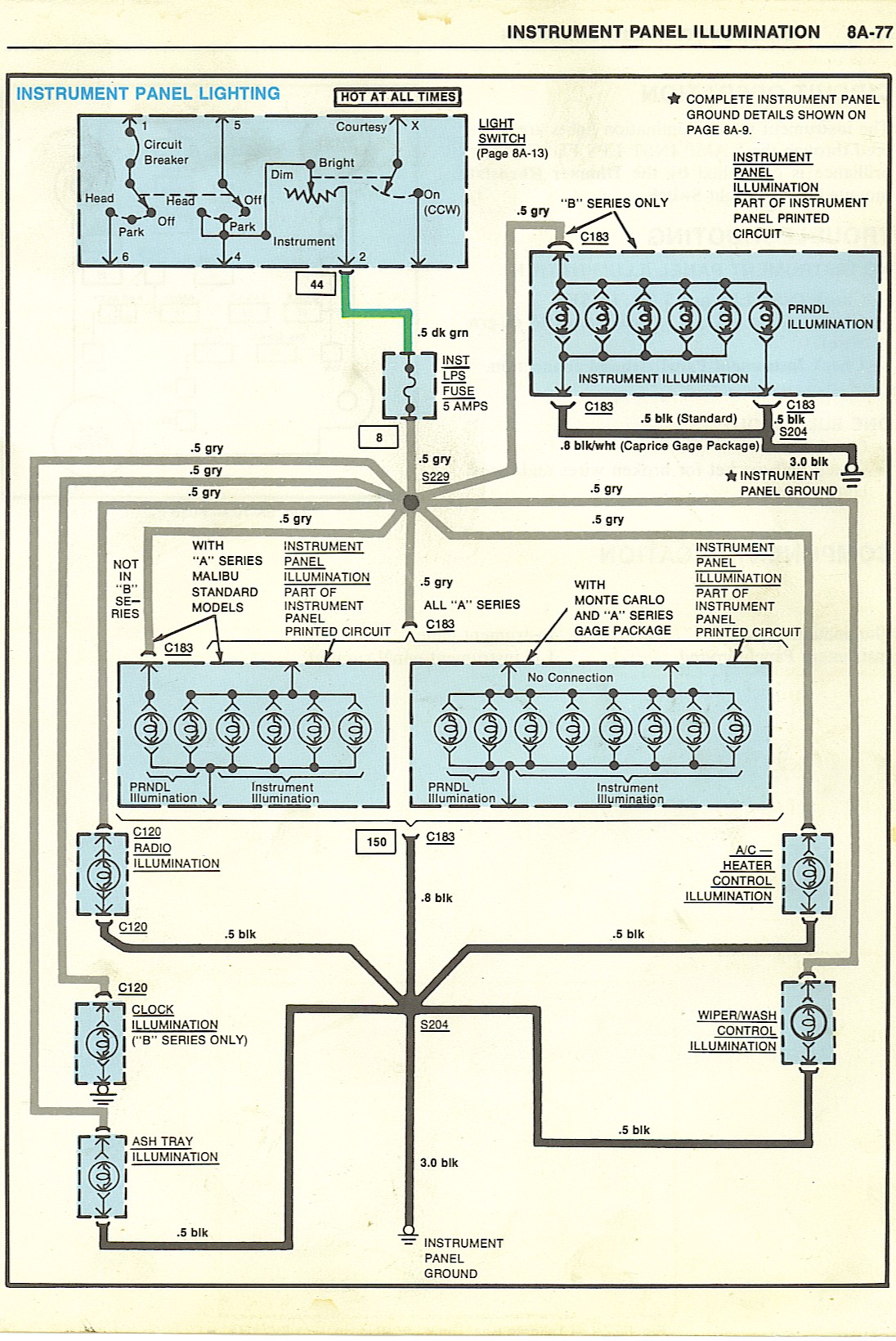
G body Gauge Cluster Wiring Diagram
G body Gauge Cluster Wiring Diagram is a crucial tool for understanding the electrical connections within your vehicle’s gauge cluster. Whether you are installing a new gauge cluster or troubleshooting electrical issues, having access to the wiring diagram is essential.
Why are G body Gauge Cluster Wiring Diagram essential?
- Helps in understanding the layout of the electrical connections
- Aids in identifying wire colors and their functions
- Facilitates troubleshooting of electrical problems
- Ensures proper installation of the gauge cluster
How to read and interpret G body Gauge Cluster Wiring Diagram effectively
Reading and interpreting a wiring diagram may seem daunting at first, but with a systematic approach, it can be easily understood. Here are some tips:
- Start by familiarizing yourself with the key symbols and abbreviations used in the diagram
- Follow the flow of the diagram from one component to another
- Pay attention to wire colors and their corresponding functions
- Use a highlighter or pen to mark important connections
Using G body Gauge Cluster Wiring Diagram for troubleshooting electrical problems
When faced with electrical issues in your vehicle’s gauge cluster, the wiring diagram can be a lifesaver. Here’s how you can use it for troubleshooting:
- Identify the specific area of the gauge cluster that is malfunctioning
- Trace the wiring connections related to that area in the diagram
- Check for continuity, voltage, or resistance at key points in the circuit
- Compare your findings with the expected values in the wiring diagram
Remember, the wiring diagram is your roadmap to solving electrical problems effectively.
Importance of safety when working with electrical systems
Working with electrical systems, including using wiring diagrams, requires utmost caution to prevent accidents and injuries. Here are some safety tips:
- Always disconnect the battery before working on any electrical components
- Use insulated tools to avoid electrical shocks
- Avoid working on electrical systems in wet or damp conditions
- If you are unsure about a particular wiring connection, seek professional help
By following these safety tips and best practices, you can ensure a safe and successful experience when using G body Gauge Cluster Wiring Diagram.
G body Gauge Cluster Wiring Diagram
5+ g-body gauge cluster wiring diagram – ArminderRuno

g-body gauge cluster wiring diagram – MehreanKelsea

3.8 to 350 SBO swap/ gauge wiring question | GBodyForum – 1978-1988 GM

5+ g-body gauge cluster wiring diagram – DonaldaMaythu

G Body Engine Wiring Diagram and Wiring Diagrams – 10+ G Body Engine

A/G BODY WIRING DIAGRAMS – MalibuRacing.com
