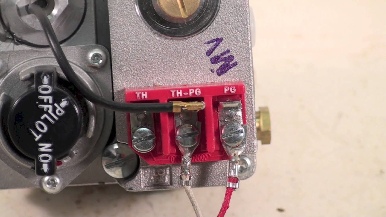
A gas valve wiring diagram is a crucial tool for understanding the electrical connections within a gas valve system. It provides a visual representation of how the wires are connected and helps ensure that the system functions properly. By referring to a wiring diagram, technicians can troubleshoot issues, identify faulty connections, and make necessary repairs.
Why Gas Valve Wiring Diagrams are Essential
Gas valve wiring diagrams are essential for several reasons:
- Help in understanding the electrical connections within the system
- Aid in troubleshooting electrical issues
- Ensure proper installation and operation of the gas valve system
How to Read and Interpret Gas Valve Wiring Diagrams
Reading and interpreting gas valve wiring diagrams can be daunting for those unfamiliar with electrical systems. Here are a few tips to help you navigate through the diagram effectively:
- Identify the components: Understand the various components within the diagram and their corresponding symbols.
- Follow the wiring: Trace the wires from one component to another to understand how they are connected.
- Refer to the legend: The legend on the diagram provides information on the symbols used and their meanings.
Using Gas Valve Wiring Diagrams for Troubleshooting
Gas valve wiring diagrams are invaluable for troubleshooting electrical problems. Here’s how you can utilize them effectively:
- Identify faulty connections: By following the wiring diagram, you can pinpoint any faulty connections that may be causing issues.
- Check for continuity: Use a multimeter to test the continuity of the wires and ensure they are properly connected.
- Refer to the manufacturer’s instructions: The wiring diagram should align with the manufacturer’s instructions for the gas valve system.
Importance of Safety
When working with gas valve wiring diagrams and electrical systems, safety should be a top priority. Here are some safety tips to keep in mind:
- Turn off power: Always turn off the power supply before working on any electrical system to prevent electric shock.
- Use insulated tools: Insulated tools can help prevent electrical shock when working with live wires.
- Wear protective gear: Wear appropriate safety gear, such as gloves and goggles, to protect yourself from potential hazards.
Gas Valve Wiring Diagram
Robertshaw Gas Valve Wiring Diagram – Easy Wiring

White Rodgers Gas Valve Wiring Diagram – Gas Control Valve Wiring

Millivolt Gas Valve Wiring Diagram

Honeywell 2 Zone Valve Wiring Diagram For Your Needs

How to replace Honeywell Gas control valve:

Robertshaw Gas Valve Wiring Diagram
