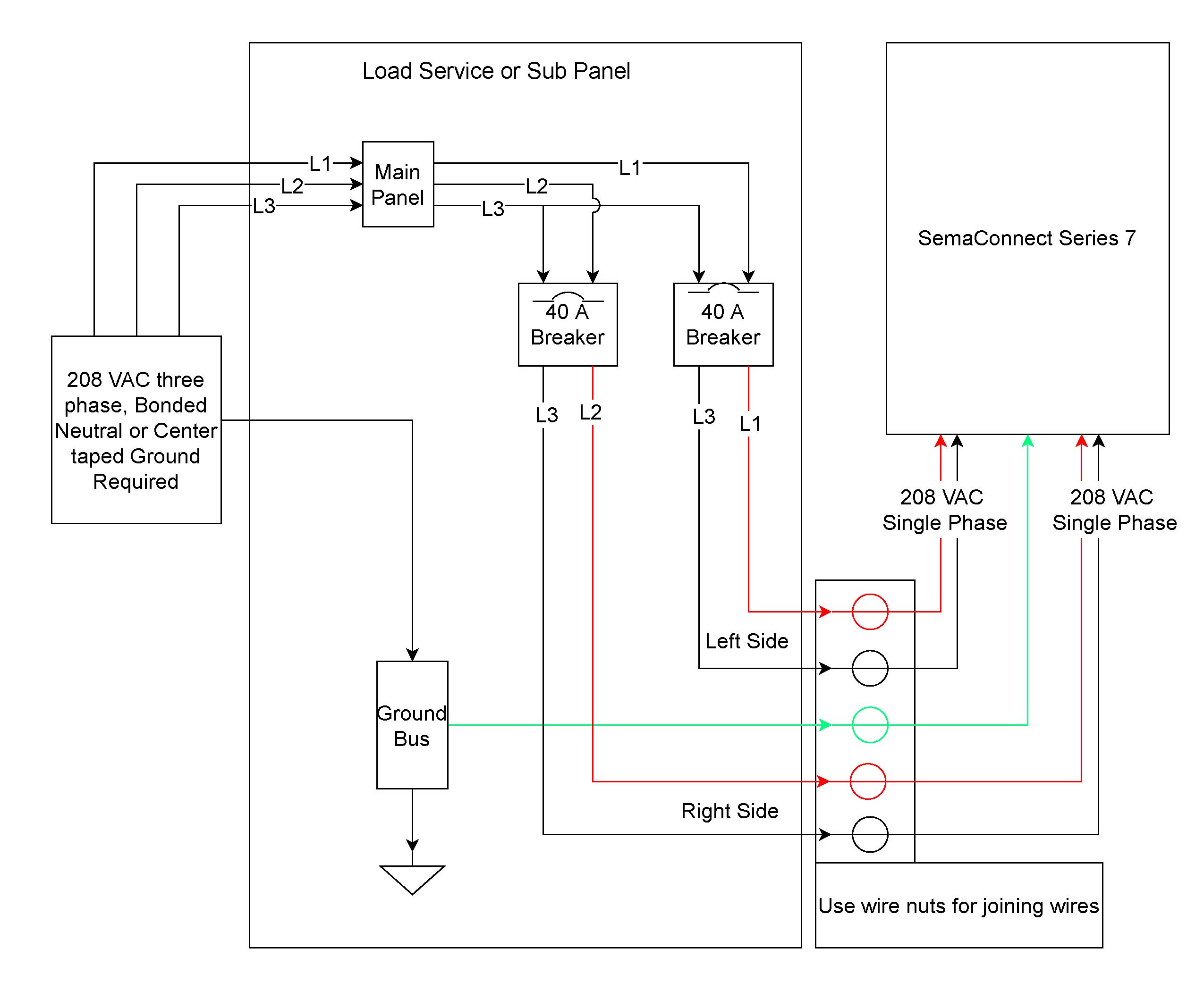
When it comes to installing aftermarket gauges in your vehicle, understanding the Glowshift Gauge Wiring Diagram is crucial. These diagrams provide a visual representation of how the gauges should be connected to the electrical system of your vehicle, ensuring proper functionality and accurate readings.
Importance of Glowshift Gauge Wiring Diagram
Here are a few reasons why Glowshift Gauge Wiring Diagrams are essential:
- They help you identify the correct wires for connecting the gauges.
- They ensure that the gauges are properly grounded for accurate readings.
- They prevent damage to the gauges and the vehicle’s electrical system.
Reading and Interpreting Glowshift Gauge Wiring Diagram
Reading and interpreting Glowshift Gauge Wiring Diagrams may seem daunting at first, but with a little practice, you can easily understand them. Here’s how:
- Start by identifying the different components of the diagram, such as the gauges, wires, and connections.
- Follow the lines in the diagram to see how the different components are connected.
- Pay attention to the color codes of the wires to ensure they are connected correctly.
Using Glowshift Gauge Wiring Diagram for Troubleshooting
Glowshift Gauge Wiring Diagrams can also be used for troubleshooting electrical problems in your vehicle. By referring to the diagram, you can easily identify any faulty connections or components that may be causing issues with your gauges.
Safety Tips
Working with electrical systems can be dangerous if proper precautions are not taken. Here are some safety tips to keep in mind when using Glowshift Gauge Wiring Diagrams:
- Always disconnect the battery before working on the electrical system of your vehicle.
- Avoid working on the electrical system in wet or damp conditions to prevent the risk of electric shock.
- Use insulated tools to prevent short circuits and electrical hazards.
Glowshift Gauge Wiring Diagram
Glowshift Trans Temp Gauge Wiring Diagram

Glowshift Water Temp Gauge Wiring Diagram

Glowshift Gauge Wiring Diagram

glowshift volt gauge wiring diagram – Wiring Diagram and Schematics

Glowshift Gauge Wiring Diagram Explained – Moo Wiring

Glowshift Fuel Pressure Gauge Wiring Diagram – Greenus
