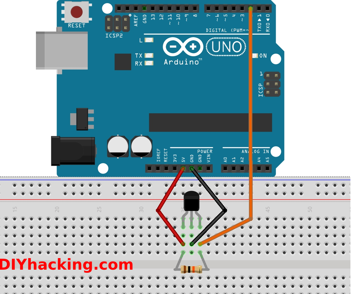
When it comes to understanding the intricacies of electrical systems in vehicles or machinery, having a clear grasp of the Hall Effect Sensor Wiring Diagram is crucial. This diagram provides a visual representation of how the Hall Effect sensor is connected within the system, allowing for accurate troubleshooting and efficient repairs.
Why are Hall Effect Sensor Wiring Diagrams Essential?
Hall Effect Sensor Wiring Diagrams are essential for several reasons:
- Provide a visual representation of the sensor’s connection points
- Help in identifying potential wiring issues or faults
- Aid in understanding how the sensor interacts with other components in the system
How to Read and Interpret Hall Effect Sensor Wiring Diagrams
Reading and interpreting Hall Effect Sensor Wiring Diagrams can be simplified by following these steps:
- Identify the sensor location in the diagram
- Trace the wiring connections from the sensor to the main system
- Understand the color-coding and symbols used in the diagram
Using Hall Effect Sensor Wiring Diagrams for Troubleshooting
When facing electrical problems, Hall Effect Sensor Wiring Diagrams can be invaluable for troubleshooting. Here’s how:
- Check for continuity in the wiring connections
- Verify proper voltage supply to the sensor
- Look for any signs of damage or wear in the wiring
Importance of Safety
Working with electrical systems requires utmost caution to prevent accidents or damage. Here are some safety tips to keep in mind:
- Always disconnect the power source before working on any electrical component
- Use insulated tools to avoid electric shock
- Double-check connections before powering up the system
Hall Effect Sensor Wiring Diagram
A Simple Guide to Using a Hall Effect Sensor With Arduino

Wiring the 314X Hall Effect Sensor Module | 14core.com

Using a Hall Effect Sensor with Arduino – Electronics-Lab

Interfacing SS49E Linear Hall Effect Sensor Module with Arduino

Interfacing A3144 Hall Effect Sensor with Arduino UNO

Interfacing Hall Effect sensor with Arduino – Hackster.io
