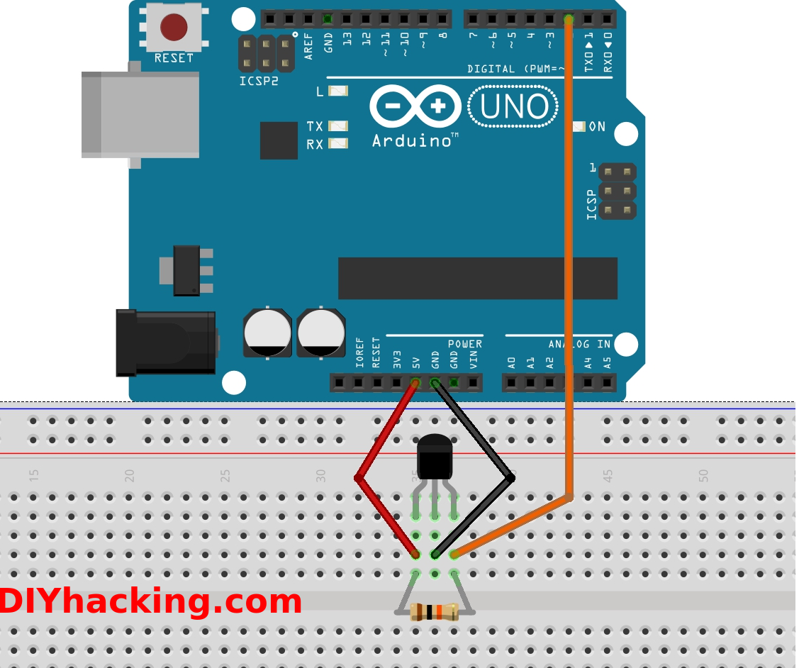
When it comes to understanding the intricacies of electrical systems in vehicles or machinery, having a clear Hall Sensor Wiring Diagram can make all the difference. This diagram serves as a roadmap for the various components and connections involved in the hall sensor circuit, allowing technicians to troubleshoot, repair, or modify the system with ease.
Importance of Hall Sensor Wiring Diagram
- Provides a visual representation of the hall sensor circuit
- Helps identify the location of components and connections
- Aids in understanding the flow of electricity within the system
- Essential for diagnosing and fixing electrical issues
Reading and Interpreting Hall Sensor Wiring Diagram
Reading a Hall Sensor Wiring Diagram may seem daunting at first, but with a bit of practice, it can become second nature. Here are some key tips to help you navigate through the diagram effectively:
- Understand the symbols and abbreviations used in the diagram
- Follow the flow of electricity from the power source to the hall sensor and back
- Identify the color codes for wires to ensure correct connections
- Pay attention to the labeling of components for easy reference
Using Hall Sensor Wiring Diagram for Troubleshooting
When faced with electrical problems in a hall sensor circuit, the wiring diagram can be your best friend. By following these steps, you can effectively troubleshoot and resolve issues:
- Check for loose or disconnected wires indicated in the diagram
- Verify proper voltage levels at different points in the circuit
- Inspect components for signs of damage or wear
- Use a multimeter to test continuity and resistance in the circuit
Remember, safety should always be a top priority when working with electrical systems. Here are some important tips to keep in mind:
- Always disconnect power source before working on any electrical system
- Use insulated tools to prevent electrical shock
- Avoid working on wet surfaces or in damp conditions
- Wear appropriate protective gear, such as gloves and goggles
Hall Sensor Wiring Diagram
A Simple Guide to Using a Hall Effect Sensor With Arduino

Wiring the 314X Hall Effect Sensor Module | 14core.com

Using a Hall Effect Sensor with Arduino – Electronics-Lab.com

Hall Sensor Tutorial for Arduino, ESP8266 and ESP32

Hall Sensor Tutorial for Arduino, ESP8266 and ESP32

Interfacing SS49E Linear Hall Effect Sensor Module with Arduino
