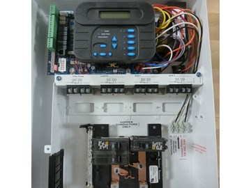
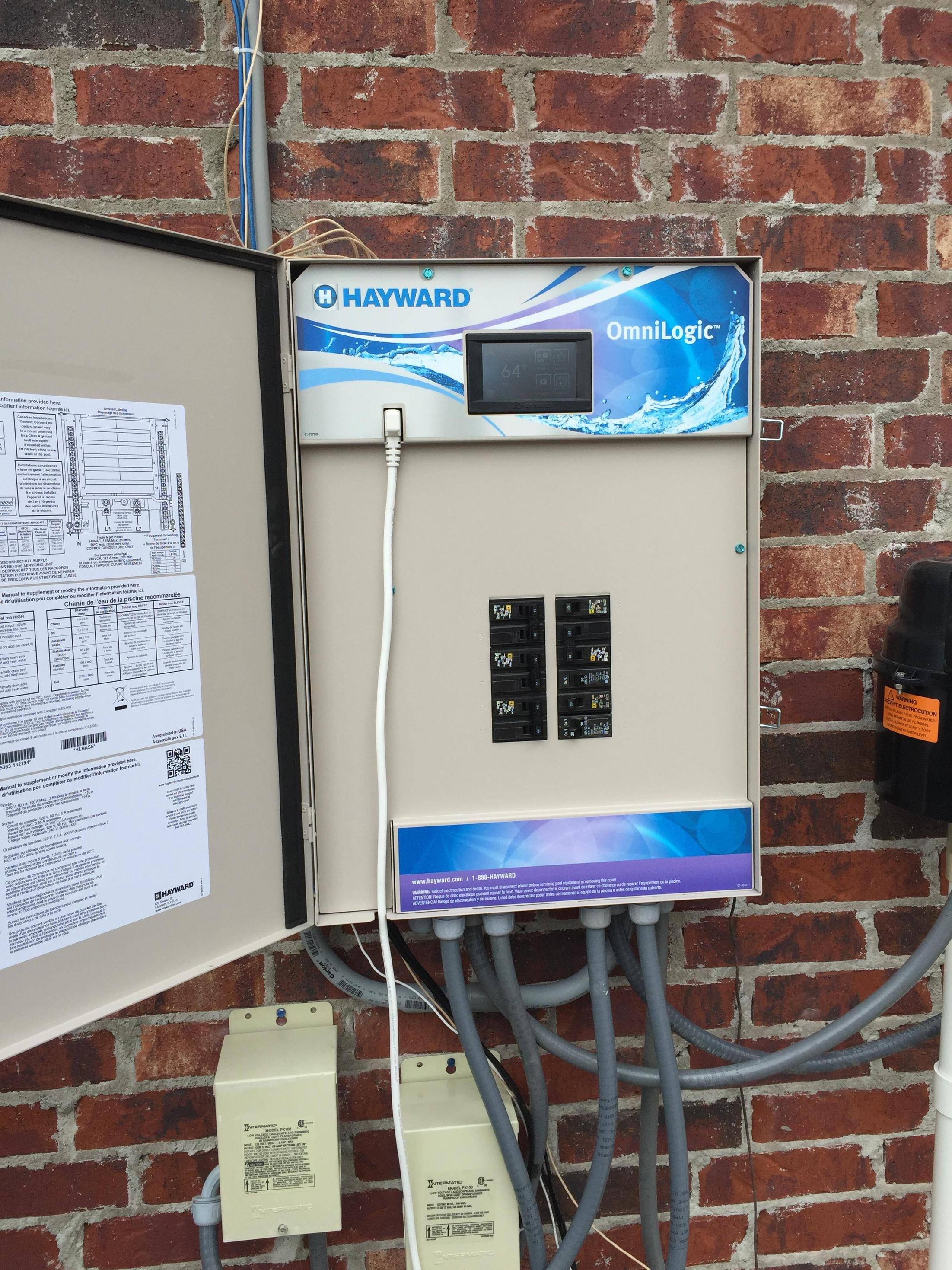
Hayward Pro Logic Wiring Diagrams are essential tools for anyone working with electrical systems. These diagrams provide a visual representation of the wiring connections within a Hayward Pro Logic system, helping users understand the layout and configuration of the various components.
Importance of Hayward Pro Logic Wiring Diagrams
- Ensure proper installation of the system
- Facilitate troubleshooting and repairs
- Help prevent electrical hazards
Reading and Interpreting Hayward Pro Logic Wiring Diagrams
When reading a Hayward Pro Logic Wiring Diagram, it’s important to pay attention to the symbols and labels used to represent different components. The diagram will typically include color-coded wires, terminal connections, and component locations. By following the lines and symbols on the diagram, users can trace the flow of electrical current and identify potential issues.
Using Hayward Pro Logic Wiring Diagrams for Troubleshooting
- Identify the source of electrical problems
- Check for loose connections or damaged wires
- Verify proper voltage levels at different points in the system
Safety Tips for Working with Hayward Pro Logic Wiring Diagrams
- Always turn off power before working on electrical systems
- Use insulated tools to prevent electric shock
- Double-check connections before powering up the system
- Consult a professional if unsure about any aspect of the wiring diagram
Hayward Pro Logic Wiring Diagram
How to Wire 115V Equipment to the Hayward Pro Logic – INYOPools.com

How To Wire A 2-Speed 230V Motor to a Hayward Pro Logic System

How to Wire 230V Equipment to the Hayward Pro Logic – INYOPools.com

Hayward Pro Logic Wiring Diagram

Hayward Pro Logic Wiring Diagram

Hayward Pro Logic Wiring Diagram
