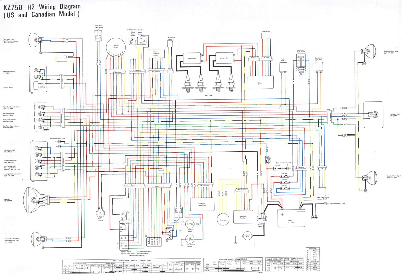
Are you looking for information on John Deere 345 Wiring Diagram? Understanding the wiring diagram for your John Deere 345 is crucial for troubleshooting electrical issues and ensuring proper maintenance of your equipment. Let’s delve into the importance of these diagrams and how to effectively interpret them.
Why John Deere 345 Wiring Diagrams are Essential
John Deere 345 Wiring Diagrams are essential for several reasons:
- Provide a visual representation of the electrical system in your equipment
- Help in identifying the various components and their connections
- Guide in troubleshooting electrical issues efficiently
How to Read and Interpret John Deere 345 Wiring Diagrams
Reading and interpreting wiring diagrams can seem daunting at first, but with the right approach, it can be a useful tool:
- Start by familiarizing yourself with the symbols used in the diagram
- Follow the flow of the electrical circuit from the power source to the components
- Identify any switches, relays, or connectors that may affect the circuit
Using John Deere 345 Wiring Diagrams for Troubleshooting
Wiring diagrams are invaluable for troubleshooting electrical problems in your John Deere 345. Here’s how you can use them effectively:
- Trace the path of the electrical current to pinpoint any potential issues
- Check for continuity and voltage at various points in the circuit
- Compare the actual wiring with the diagram to identify any discrepancies
Importance of Safety
Working with electrical systems can be hazardous if proper precautions are not taken. Here are some safety tips to keep in mind:
- Always disconnect the power source before working on any electrical components
- Use insulated tools to prevent electrical shock
- Avoid working on electrical systems in wet or damp conditions
- Refer to the manufacturer’s safety guidelines before attempting any repairs
John Deere 345 Wiring Diagram
john deere 345 wiring diagram – Wiring Diagram

john deere 345 wiring diagram – Wiring Diagram
John Deere 345 Lawn Tractor Wiring Diagram – Wiring Diagram

Wiring Diagram For John Deere 345 – Wiring Digital and Schematic
John Deere 345 Lawn Tractor Wiring Diagram – Wiring Diagram

John Deere Gx345 Wiring Diagram – Wiring Diagram
