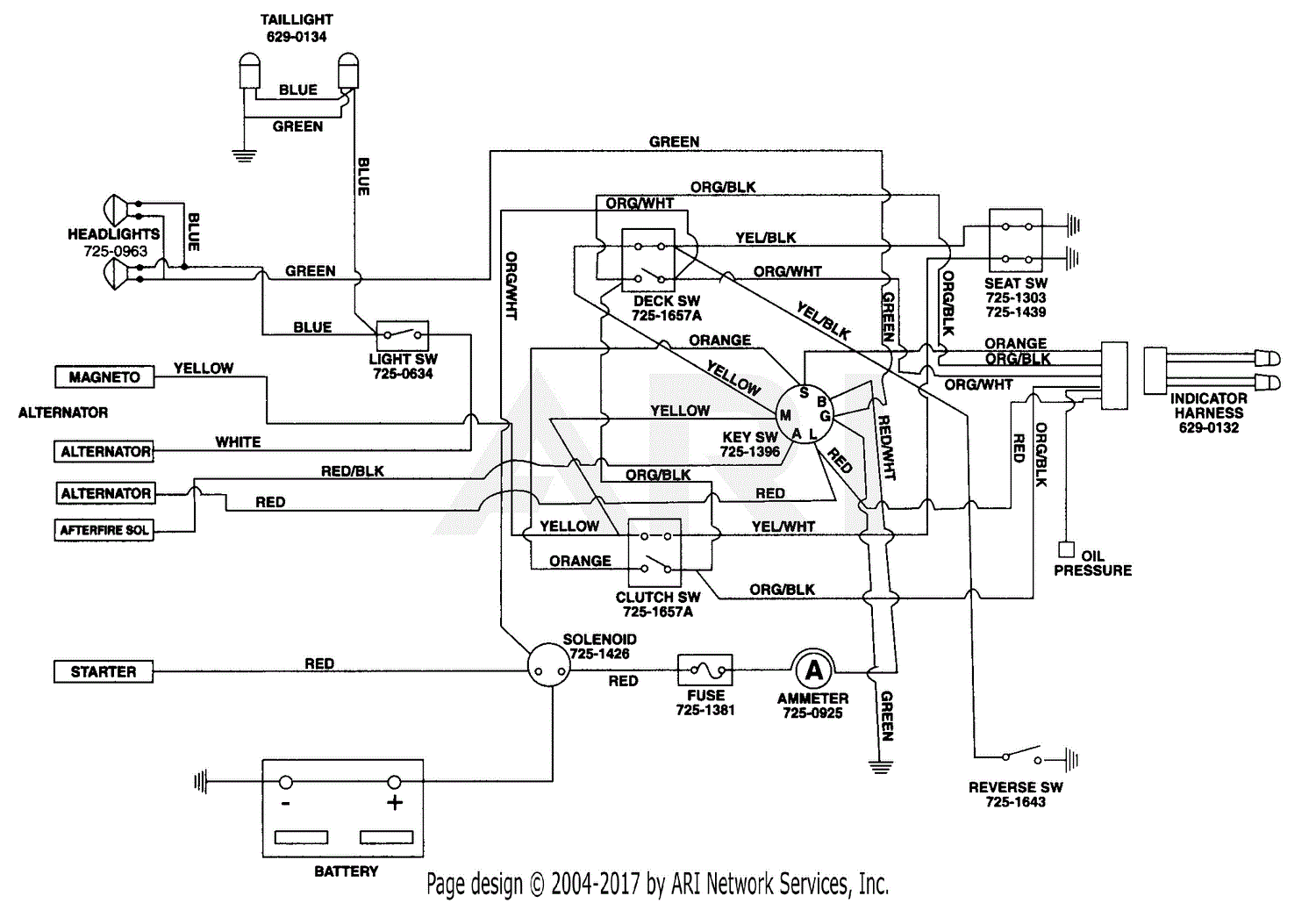
When it comes to maintaining and repairing John Deere equipment, having access to accurate wiring diagrams is essential. A John Deere Wiring Diagram provides a detailed schematic of the electrical system in a piece of equipment, helping mechanics and technicians troubleshoot and repair electrical issues effectively.
Why John Deere Wiring Diagrams are essential
- Ensure proper electrical connections
- Identify components and their locations
- Aid in diagnosing electrical issues
- Prevent damage to the electrical system
Reading and interpreting John Deere Wiring Diagrams
John Deere Wiring Diagrams may seem complex at first, but with practice, they can be a valuable tool in troubleshooting electrical problems. Here are some tips for reading and interpreting them effectively:
- Start by identifying the key components in the diagram, such as the battery, starter, alternator, and various switches.
- Understand the symbols and color codes used in the diagram to represent different electrical components.
- Follow the flow of electricity through the system to pinpoint potential issues.
Using John Deere Wiring Diagrams for troubleshooting
John Deere Wiring Diagrams are invaluable when it comes to troubleshooting electrical problems in equipment. By following the wiring diagram and conducting tests on the electrical system, technicians can identify and resolve issues such as faulty connections, damaged wires, or malfunctioning components.
Importance of safety
Working with electrical systems can be dangerous, so it is crucial to prioritize safety when using wiring diagrams. Here are some safety tips and best practices to keep in mind:
- Always disconnect the battery before working on the electrical system.
- Use insulated tools to avoid electric shocks.
- Avoid working on electrical systems in wet or damp conditions.
- Double-check all connections before re-energizing the system.
John Deere Wiring Diagram
John Deere Gt235 Wiring Diagram – Wiring Diagram Pictures

John Deere La105 Wiring Diagram

John Deere 4600 Series Tractor Wiring Diagram – Wiring Diagram Pictures

John deere x320 wiring diagram

John Deere Gt262 Wiring Diagram – Wiring Diagram Pictures

John Deere Lt155 Wiring Diagram With Electric Clutch
