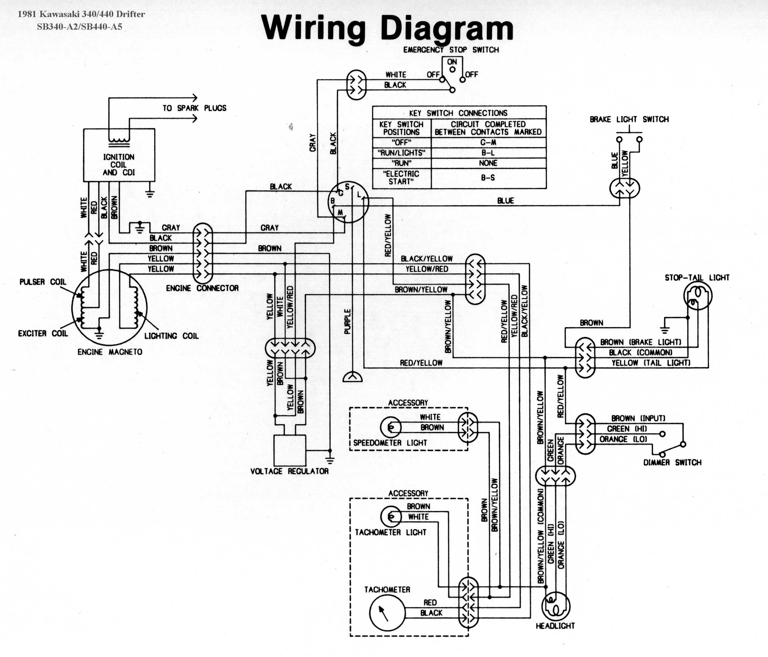
Kawasaki Mule 4010 Wiring Diagram
When it comes to understanding the electrical system of your Kawasaki Mule 4010, having a wiring diagram can be incredibly helpful. A wiring diagram is a detailed illustration of the electrical connections and components within the vehicle, allowing you to troubleshoot issues, make repairs, and perform maintenance tasks effectively.
Why Kawasaki Mule 4010 Wiring Diagrams are essential
- Provide a visual representation of the electrical system
- Help in identifying components and their connections
- Aid in troubleshooting electrical issues
- Guide in performing maintenance and repairs
How to read and interpret Kawasaki Mule 4010 Wiring Diagrams effectively
- Start by familiarizing yourself with the key symbols and color codes used in the diagram
- Follow the flow of the wiring from one component to another
- Pay attention to the labels and legends for better understanding
Using Kawasaki Mule 4010 Wiring Diagrams for troubleshooting electrical problems
- Identify the specific circuit or component that is causing the issue
- Trace the wiring to check for any loose connections, breaks, or damage
- Refer to the diagram to understand how the electrical system is supposed to function
It is important to note that working with electrical systems can be dangerous if proper precautions are not taken. When using Kawasaki Mule 4010 Wiring Diagrams, always prioritize safety by following these tips:
- Disconnect the battery before working on any electrical components
- Use insulated tools to prevent electric shocks
- Avoid working on the wiring when the vehicle is running or the key is in the ignition
- If you are unsure about any electrical task, seek professional help
Kawasaki Mule 4010 Wiring Diagram
Kawasaki Mule 4010 Wiring Schematic
Kawasaki Mule 4010 Wiring Diagram – Wiring Digital and Schematic
Kawasaki Mule 4010 Wiring Diagram – Wiring Diagram

26 Kawasaki Mule 4010 Wiring Diagram – Wiring Database 2020
Kawasaki Mule 4010 Wiring Diagram – Wiring Draw And Schematic
Kawasaki Mule 4010 Wiring Diagram – Wiring Diagram
