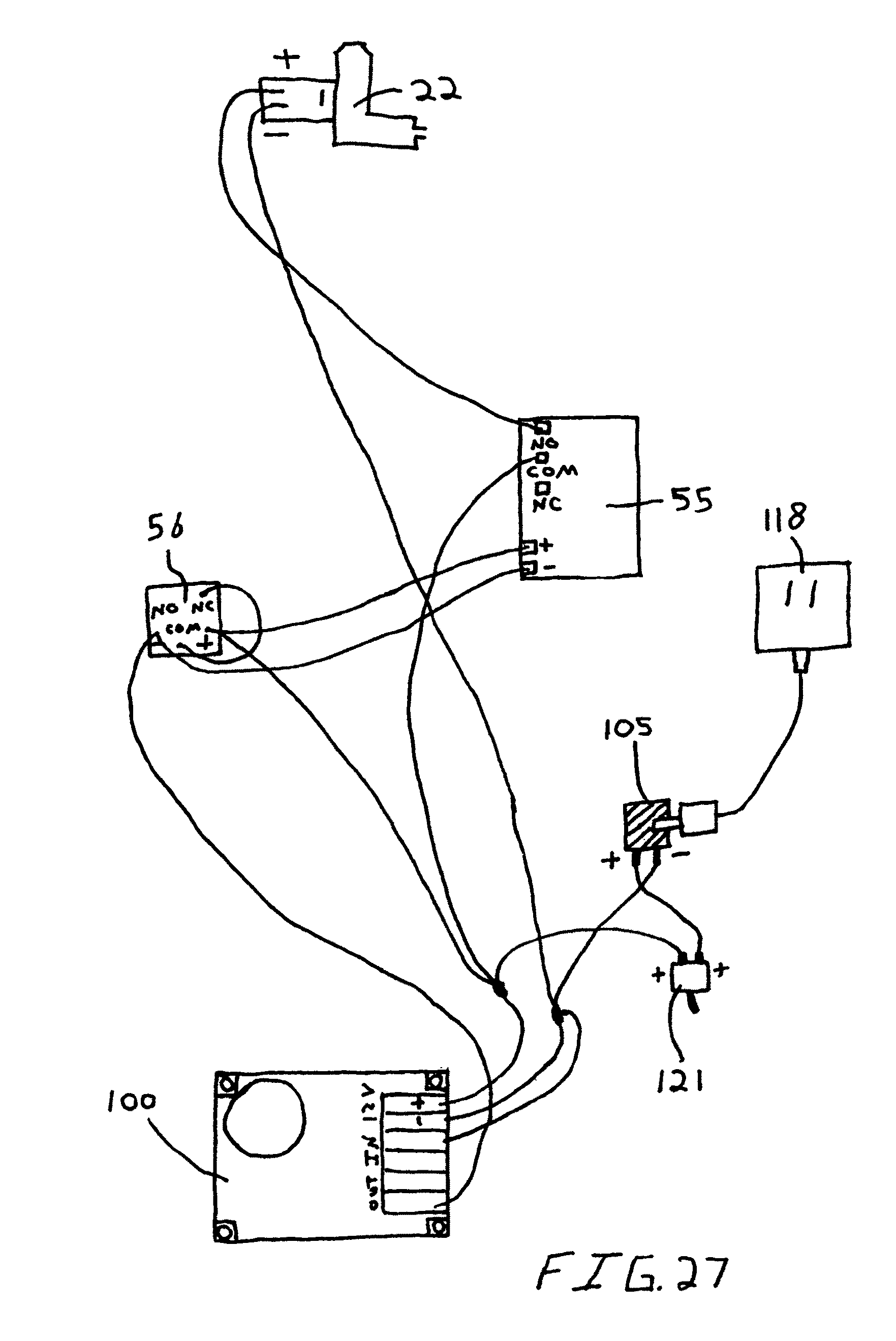
When it comes to understanding electrical systems in buildings or appliances, having a clear and detailed L5 30 wiring diagram is crucial. These diagrams provide a visual representation of the electrical connections and components involved in a specific circuit, allowing electricians and DIY enthusiasts to easily follow the wiring layout and make necessary repairs or installations.
Importance of L5 30 Wiring Diagrams
- Ensure correct wiring connections
- Prevent short circuits or electrical hazards
- Facilitate troubleshooting and repairs
- Comply with electrical codes and regulations
Reading and Interpreting L5 30 Wiring Diagrams
Reading a wiring diagram may seem daunting at first, but with a little practice, you can easily decipher the symbols and lines to understand the circuit layout. Here are some tips to help you read and interpret L5 30 wiring diagrams effectively:
- Identify the components and connections labeled in the diagram
- Follow the flow of current from the power source to the load
- Pay attention to symbols representing switches, outlets, and other devices
- Use color codes and labeling to differentiate between wires and connections
Using L5 30 Wiring Diagrams for Troubleshooting
When faced with electrical problems, a wiring diagram can be your best friend in identifying the root cause of the issue. By following the circuit layout and checking for continuity or voltage at various points, you can pinpoint the faulty component or connection that needs attention. Here’s how you can use L5 30 wiring diagrams for troubleshooting:
- Trace the path of the current and check for breaks or interruptions
- Test individual components for proper functioning using a multimeter
- Compare the actual wiring with the diagram to spot any discrepancies
- Consult the manufacturer’s instructions or technical support for specific guidance
Safety Tips for Working with Electrical Systems
When working with electrical systems and using wiring diagrams, safety should always be your top priority. Here are some essential safety tips and best practices to keep in mind:
- Turn off the power supply before starting any work on the circuit
- Use insulated tools and equipment to prevent electric shocks
- Wear appropriate protective gear, such as gloves and goggles, to avoid injuries
- Double-check your connections and wiring before energizing the circuit
L5 30 Wiring Diagram
NEMA L5-30 Power Flanged Inlet Receptacle 3P, 30 A, 125/250 V, Integra

L5 30 Plug Wiring Diagram

L5 30r Wiring Diagram

Nema L5-30 Wiring Diagram

Nema L5-30 Wiring Diagram – Wiring Diagram Pictures

Nema L5-30 Wiring Diagram – Wiring Diagram Pictures
