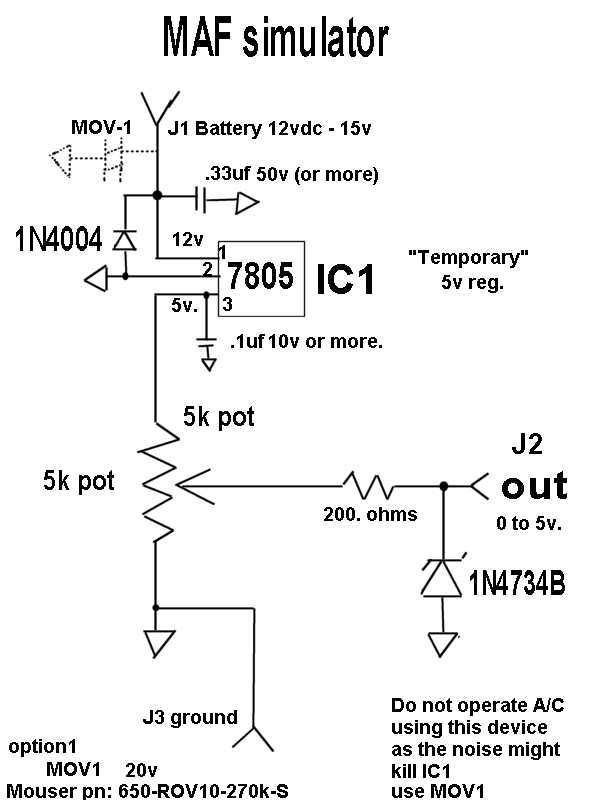
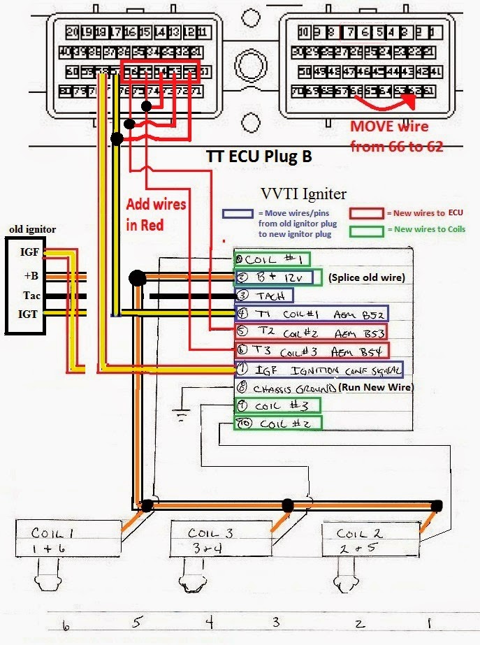
When it comes to understanding the inner workings of your vehicle’s engine, having a clear understanding of the Maf Sensor Wiring Diagram is crucial. The Maf Sensor Wiring Diagram provides a detailed visual representation of the wiring connections for the Mass Airflow Sensor (MAF) in your vehicle. This diagram is essential for anyone looking to troubleshoot electrical issues or make modifications to their vehicle’s engine.
Why Maf Sensor Wiring Diagrams are Essential
The Maf Sensor Wiring Diagram is essential for a number of reasons:
- It provides a visual guide to the wiring connections for the MAF sensor, helping you identify and understand each wire’s function.
- It allows you to troubleshoot electrical issues more effectively, as you can trace the wiring connections and pinpoint any potential problems.
- It is a valuable tool for anyone looking to make modifications or upgrades to their vehicle’s engine, as it ensures proper wiring connections are maintained.
Reading and Interpreting Maf Sensor Wiring Diagrams
Reading and interpreting Maf Sensor Wiring Diagrams may seem daunting at first, but with the right approach, it can be a straightforward process:
- Start by familiarizing yourself with the key components of the diagram, such as the MAF sensor, power source, and ground connections.
- Follow the wiring lines to trace the connections and understand how each wire is linked to the MAF sensor.
- Refer to the color codes or labels on the diagram to identify specific wires and their functions.
Using Maf Sensor Wiring Diagrams for Troubleshooting
Maf Sensor Wiring Diagrams are invaluable tools for troubleshooting electrical problems in your vehicle:
- By following the wiring connections on the diagram, you can identify any loose connections, damaged wires, or faulty components that may be causing issues.
- You can use the diagram to test the continuity of each wire and ensure that all connections are secure and functioning properly.
- Referencing the Maf Sensor Wiring Diagram can help you isolate and resolve electrical issues more efficiently, saving you time and money in the long run.
Importance of Safety
When working with electrical systems and using wiring diagrams, it is crucial to prioritize safety:
- Always disconnect the battery before working on any electrical components to prevent the risk of electric shock.
- Use insulated tools and wear protective gear, such as gloves and safety goggles, to minimize the risk of injury.
- Double-check all connections and ensure that all wiring is done correctly to prevent potential hazards or damage to your vehicle.
Maf Sensor Wiring Diagram
Maf Sensor Wiring Diagram Schematic

Bosch 0281002735 Maf Sensor Wiring Diagram

How to Read and Understand a MAF Sensor Wiring Diagram

bosch maf sensor wiring diagram manual shop – bablusa

What are the two wire on the 6 wire IAT / MAF sensor connector that

Toyota Maf Sensor Wiring Diagram – Eco Inc
