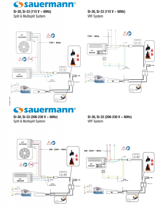
Mini Split Condensate Pump Wiring Diagrams are essential tools for understanding the electrical connections and components within a mini split system. These diagrams provide a visual representation of how the condensate pump is wired, helping technicians troubleshoot issues and ensure proper installation.
Importance of Mini Split Condensate Pump Wiring Diagrams
- Ensure proper installation of the condensate pump
- Identify and troubleshoot electrical issues
- Understand the wiring connections and components
- Ensure safety and compliance with electrical codes
Reading and Interpreting Mini Split Condensate Pump Wiring Diagrams
When reading a wiring diagram for a mini split condensate pump, it is important to understand the symbols and color codes used. Each wire is typically labeled with a specific color, and there are symbols representing different components such as relays, switches, and motors. By following the lines and connections on the diagram, technicians can identify how the system is wired and diagnose any issues.
Using Wiring Diagrams for Troubleshooting
Mini Split Condensate Pump Wiring Diagrams are invaluable for troubleshooting electrical problems in a mini split system. By referencing the diagram, technicians can trace the flow of electricity, check for loose connections, and identify faulty components. This allows for quick and efficient repairs, minimizing downtime and ensuring the system operates safely and efficiently.
Safety Tips for Working with Mini Split Condensate Pump Wiring Diagrams
- Always turn off power to the system before working on the wiring
- Use insulated tools to prevent electrical shock
- Wear appropriate safety gear such as gloves and goggles
- Double-check all connections before turning the power back on
Mini Split Condensate Pump Wiring Diagram
Aspen Mini Split Condensate Pump Wiring Diagram – Natureced

Aspen Mini Split Condensate Pump Wiring Diagram – Natureced

Gobi 2 Condensate Pump Wiring Diagram – Micro Wiring

mini split condensate pump wiring diagram

Mini-Split Condensate Removal Pump 115 Volt

Diversitech Mini Split Condensate Pump Wiring Diagram – Enorganic
