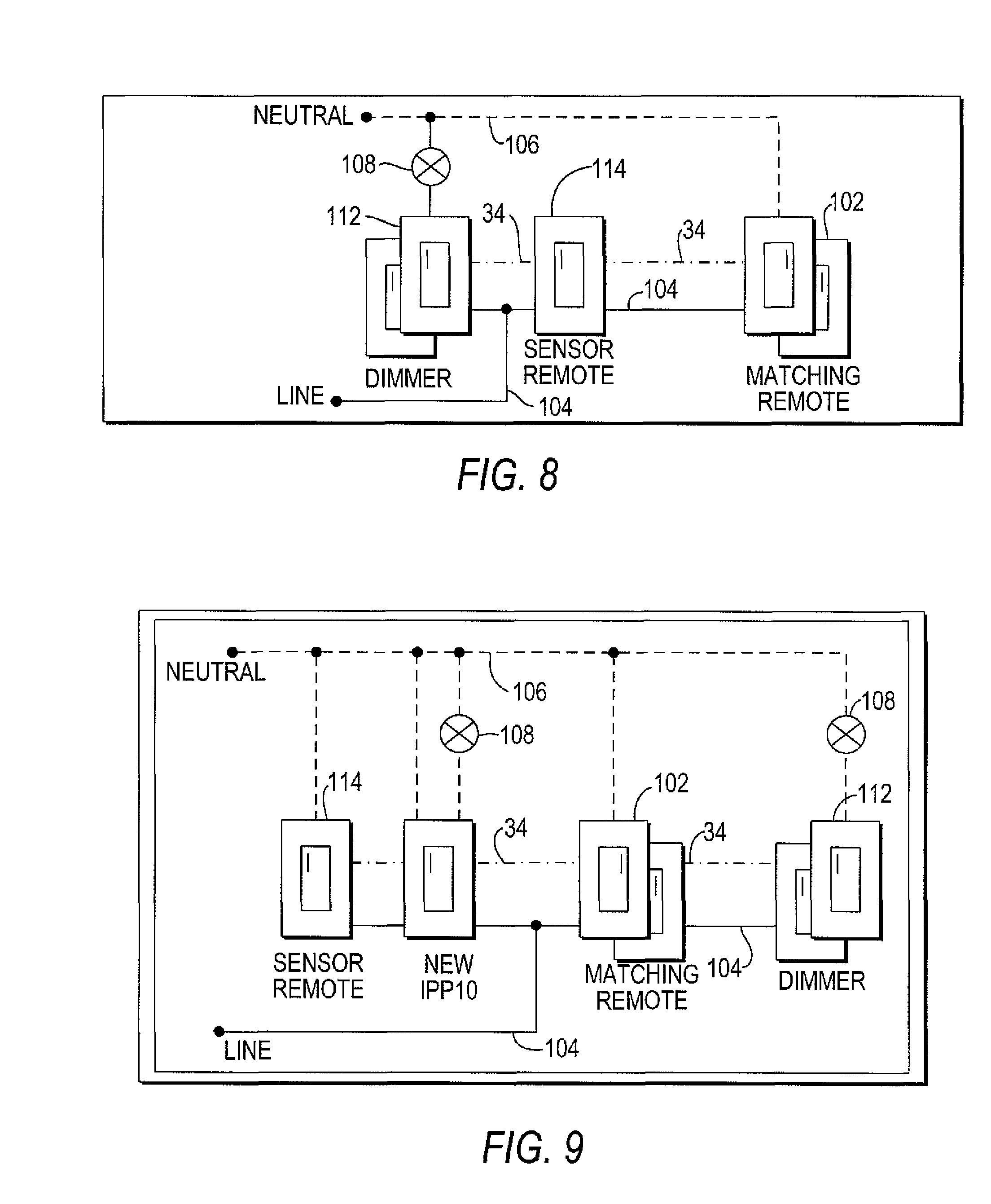
Occupancy sensor wiring diagrams are essential tools for understanding the electrical connections and configurations of occupancy sensors in a building. These diagrams provide a visual representation of how the sensors are wired and connected to the electrical system, helping technicians and electricians troubleshoot issues, make installations, and conduct maintenance.
Why Occupancy Sensor Wiring Diagrams are Essential
Occupancy sensor wiring diagrams are crucial for several reasons:
- They help identify the various components of the occupancy sensor system.
- They show the wiring connections between the sensor, power source, and lighting fixtures.
- They provide a reference for troubleshooting electrical issues related to the sensor.
- They ensure proper installation and configuration of the sensor for optimal performance.
Reading and Interpreting Occupancy Sensor Wiring Diagrams
When reading occupancy sensor wiring diagrams, it is important to pay attention to the following key components:
- Power supply connections
- Sensor input/output connections
- Lighting fixture connections
- Grounding and bonding connections
Using Occupancy Sensor Wiring Diagrams for Troubleshooting
Occupancy sensor wiring diagrams are invaluable for troubleshooting electrical problems, as they provide a roadmap for identifying faulty connections, short circuits, or other issues. By following the wiring diagram, technicians can pinpoint the source of the problem and make the necessary repairs or adjustments to restore functionality.
Safety Tips for Working with Occupancy Sensor Wiring Diagrams
When working with electrical systems and using wiring diagrams, it is important to prioritize safety:
- Always turn off the power supply before working on any electrical connections.
- Use insulated tools to prevent electric shocks.
- Double-check all connections before energizing the system to avoid potential hazards.
- Follow manufacturer’s instructions and guidelines for installation and maintenance.
Occupancy Sensor Wiring Diagram
How To Wire Motion Sensor/ Occupancy Sensors – Motion Sensor Wiring

Hubbell Occupancy Sensor Wiring Diagram

Occupancy Sensor Selection Guide 1200 Sm0701

Lutron Occupancy Sensor Wiring Diagram Gallery – Wiring Diagram Sample

Leviton Ceiling Mount Occupancy Sensor Wiring Diagram | Shelly Lighting

Lutron Ceiling Occupancy Sensor Wiring Diagram | Shelly Lighting
