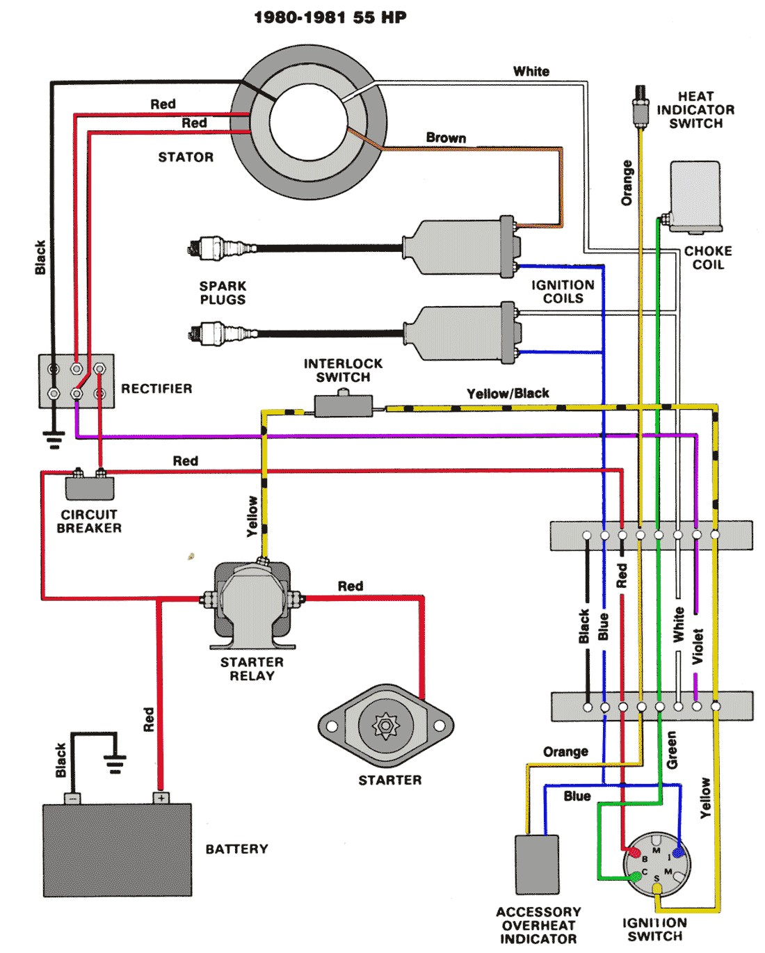
When it comes to understanding the electrical system of a vehicle or any machinery, having a clear and detailed Stator Wiring Diagram is crucial. This diagram serves as a roadmap that guides you through the wiring connections and configurations of the stator, helping you identify the various components and their functions. By following the Stator Wiring Diagram, you can effectively troubleshoot electrical issues, make necessary repairs, or even perform upgrades with confidence.
Why are Stator Wiring Diagrams essential?
Stator Wiring Diagrams are essential for several reasons:
- They provide a visual representation of the wiring connections, making it easier to understand the electrical system.
- They help in identifying the different wires, terminals, and components of the stator.
- They ensure proper installation and connection of the stator, preventing any potential electrical hazards.
- They serve as a reference guide for troubleshooting electrical issues and conducting repairs.
How to read and interpret Stator Wiring Diagrams effectively
Reading and interpreting Stator Wiring Diagrams may seem daunting at first, but with a systematic approach, you can make sense of the information provided:
- Start by identifying the key components of the stator, such as coils, windings, and terminals.
- Follow the wiring lines to understand the connections between different components.
- Pay attention to the symbols and color codes used in the diagram, as they convey important information about the wiring.
- Refer to the legend or key typically included with the diagram to interpret any specific symbols or abbreviations used.
Using Stator Wiring Diagrams for troubleshooting electrical problems
Stator Wiring Diagrams are invaluable tools for troubleshooting electrical problems in a vehicle or machinery. By following these steps, you can effectively use the diagram to diagnose and resolve issues:
- Identify the specific problem or malfunction in the electrical system.
- Refer to the Stator Wiring Diagram to locate the components and wiring related to the issue.
- Check for continuity, voltage, or resistance at different points on the stator according to the diagram.
- Compare your findings with the expected values indicated in the diagram to pinpoint the source of the problem.
Safety tips and best practices
When working with electrical systems and using Stator Wiring Diagrams, safety should always be a top priority. Here are some safety tips and best practices to keep in mind:
- Always disconnect the power source and ensure the system is de-energized before working on the wiring.
- Use appropriate personal protective equipment, such as insulated gloves and goggles, to prevent electrical shocks.
- Avoid working in wet or damp conditions to reduce the risk of electrical hazards.
- Double-check your connections and wiring before powering up the system to avoid short circuits or damage.
Stator Wiring Diagram
Understanding Stator Wiring Diagram: A Comprehensive Guide – Riley Trend

Stator Wiring Diagram – Easy Wiring

1 Cross-section of a 24-slot 4-pole outer stator with 3-phase windings
8 Pole Stator Wiring Diagram Xrm

8 Pole Stator Wiring

Color Code Motorcycle Stator Wiring Diagram
