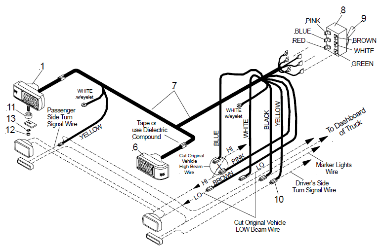
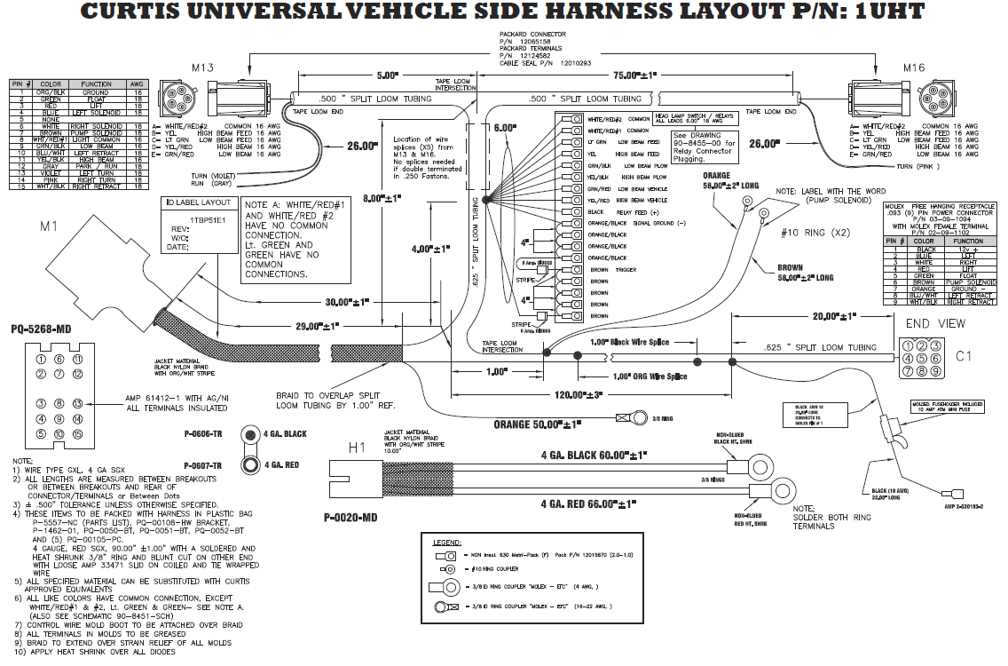
When it comes to installing or repairing a Western Unimount plow, having a clear understanding of the wiring diagram is crucial. The Western Unimount Plow Wiring Diagram provides a detailed outline of the electrical connections needed for the plow to function properly. By following the diagram, you can easily identify the different components and how they are connected, making the installation process much smoother.
Why Western Unimount Plow Wiring Diagrams are Essential
Western Unimount Plow Wiring Diagrams are essential for the following reasons:
- Helps ensure proper installation of the plow
- Allows for easy troubleshooting of electrical issues
- Provides a clear outline of how the different components are connected
Reading and Interpreting Western Unimount Plow Wiring Diagrams
When reading a Western Unimount Plow Wiring Diagram, it is important to pay attention to the following:
- Color coding of wires
- Symbols used for different components
- Direction of current flow
- Connections between components
Using Western Unimount Plow Wiring Diagrams for Troubleshooting
Western Unimount Plow Wiring Diagrams are a valuable tool for troubleshooting electrical problems. By following the diagram, you can easily identify where the issue may lie and take the necessary steps to fix it. Whether it’s a faulty connection or a damaged component, the wiring diagram provides a roadmap to help you resolve the problem efficiently.
Importance of Safety
Working with electrical systems can be dangerous, so it is crucial to prioritize safety at all times. When using wiring diagrams for Western Unimount Plows, follow these safety tips:
- Always disconnect the power source before working on the wiring
- Use insulated tools to prevent electric shock
- Avoid working in wet or damp conditions
- Double-check all connections before powering up the system
Western Unimount Plow Wiring Diagram
How To Wire A Western Unimount Snow Plow

Western Unimount Plow Lights Wiring Diagram

Western Unimount Snow Plow Wiring Diagram

western unimount plow wiring diagram – JashinConayr
9 pin western unimount plow wiring diagram

Western Plow Wiring Diagram Unimount
