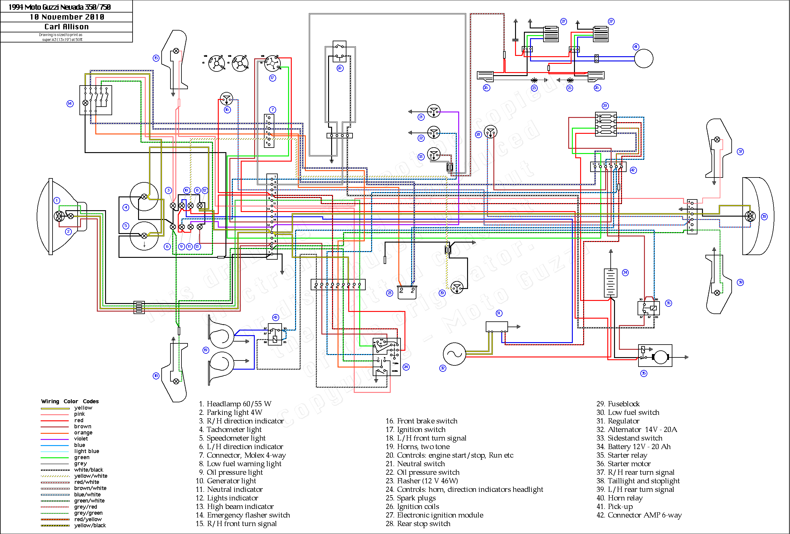
Yamaha Blaster Wiring Diagram is a crucial tool for anyone working on the electrical system of a Yamaha Blaster ATV. It provides a visual representation of the wiring layout and connections, making it easier to understand and troubleshoot any electrical issues that may arise.
Why Yamaha Blaster Wiring Diagrams are essential
- Helps in identifying wire colors and connections
- Aids in understanding the electrical system layout
- Facilitates troubleshooting electrical problems
How to read and interpret Yamaha Blaster Wiring Diagrams
When looking at a Yamaha Blaster Wiring Diagram, it’s important to understand the symbols and color codes used. Each wire is typically represented by a different color, and various symbols indicate different components such as switches, relays, and connectors. By familiarizing yourself with these symbols, you can easily follow the wiring diagram and make sense of the electrical system.
Using Yamaha Blaster Wiring Diagrams for troubleshooting
Yamaha Blaster Wiring Diagrams are invaluable when it comes to troubleshooting electrical problems. By tracing the wires and connections shown in the diagram, you can pinpoint any faults or issues within the system. This can save time and effort by providing a clear roadmap for diagnosing and fixing electrical problems.
Importance of safety when working with electrical systems
When working with electrical systems and using wiring diagrams, safety should always be a top priority. Here are some safety tips and best practices to keep in mind:
- Always disconnect the battery before working on any electrical components
- Use insulated tools to prevent electrical shocks
- Avoid working on the electrical system in wet or damp conditions
- Double-check all connections before reassembling components
- If you’re unsure or uncomfortable working with electrical systems, seek professional help
Yamaha Blaster Wiring Diagram
Yamaha Blaster 200 Wiring Diagram

Yamaha Blaster Wiring Diagram Pdf For Your Needs

Wiring Diagram Yamaha Blaster – Wiring Diagram and Schematics

2001 Yamaha Blaster Wiring Diagram Database

Yamaha Blaster Stator Wiring Diagram Collection

Yamaha Blaster 200cc Wiring Diagram – 4K Wallpapers Review
