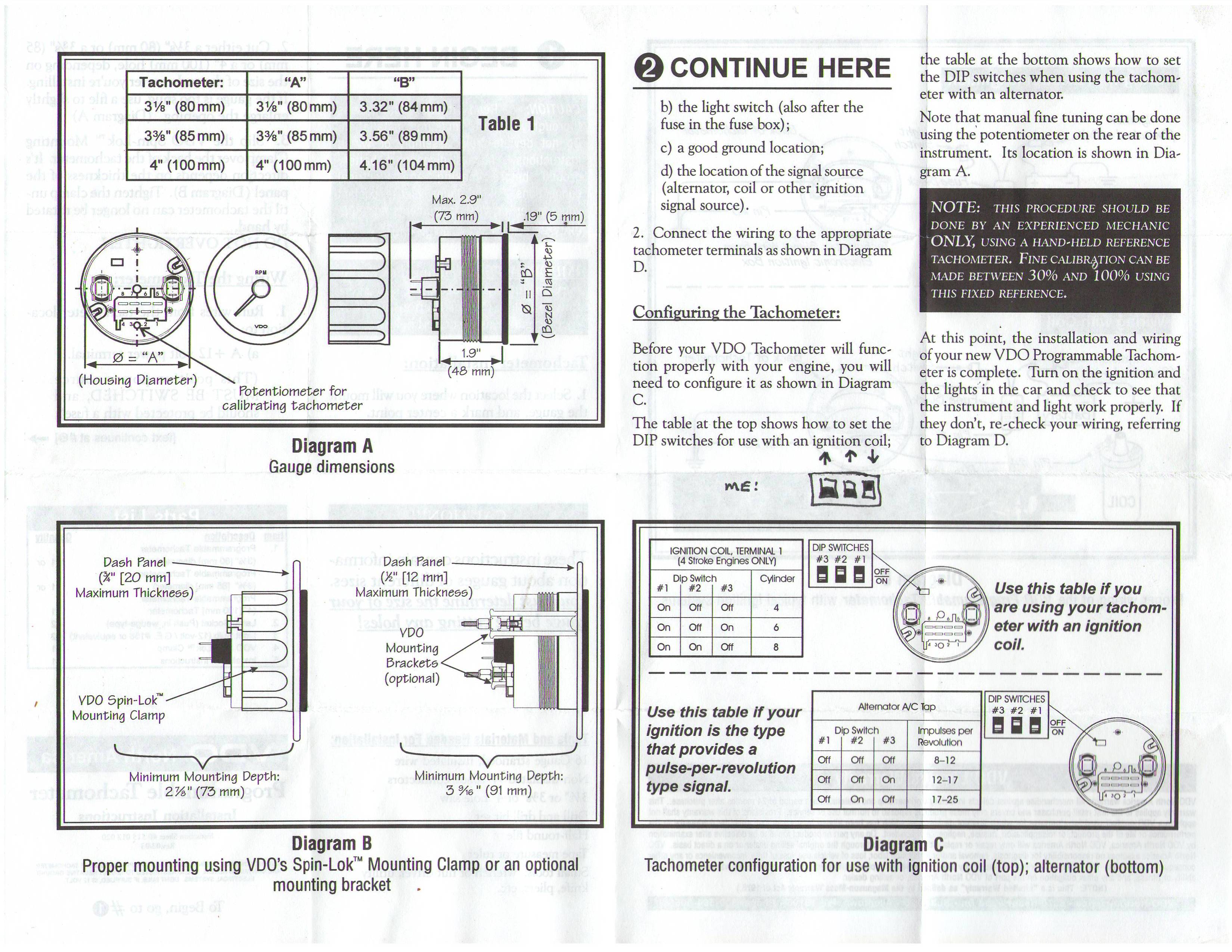
When it comes to understanding the electrical system of a vehicle, having a clear grasp of the Vdo Tacho Wiring Diagram is crucial. This diagram provides a detailed illustration of the wiring connections and layout of the tachometer in a vehicle. By studying this diagram, mechanics and enthusiasts can effectively troubleshoot electrical issues and make necessary repairs.
Importance of Vdo Tacho Wiring Diagram
- Provides a visual representation of the electrical connections
- Helps in identifying the components of the tachometer system
- Guides in understanding how signals flow through the system
- Essential for proper installation and maintenance of the tachometer
Reading and Interpreting Vdo Tacho Wiring Diagram
Reading and interpreting a Vdo Tacho Wiring Diagram may seem daunting at first, but with a systematic approach, it can be easily understood. Here are some tips to help you navigate through the diagram effectively:
- Start by identifying the key components such as the tachometer, power source, ground, and signal wires
- Follow the lines to trace the connections between the components
- Refer to the legend or key provided in the diagram for symbol meanings
- Pay attention to the color codes of the wires for accurate connection
Using Vdo Tacho Wiring Diagram for Troubleshooting
When faced with electrical problems in the tachometer system, the Vdo Tacho Wiring Diagram serves as a valuable tool for troubleshooting. By following the diagram, you can:
- Identify faulty connections or components causing the issue
- Trace the signal path to pinpoint the source of the problem
- Compare the actual wiring with the diagram to detect discrepancies
- Make informed decisions on repairs or replacements based on the diagram
Safety Tips for Working with Vdo Tacho Wiring Diagram
Working with electrical systems can be hazardous if proper precautions are not taken. Here are some safety tips to keep in mind when using Vdo Tacho Wiring Diagram:
- Always disconnect the battery before working on the electrical system
- Use insulated tools to prevent electrical shock
- Avoid working on the wiring when the engine is running
- Double-check all connections before reassembling the components
Vdo Tacho Wiring Diagram
Proper Wiring Of The Tachometer – Siemens VDO Installation And

Vdo Tacho Wiring Diagram

The Ultimate Guide to Wiring a VDO Tacho: Diagram Included!

Vdo Tachometer Wiring Diagram – Crafts Pass

VDO Performance Tachometer Installation & Operation Instructions

Vdo Marine Tachometer Wiring Diagram – IOT Wiring Diagram
